The window
This chapter names every part of Terrace's window — the ribbon, the Project browser, Next step, the plan and profile, Properties, Layers, the undo history, the command line and the status bar — and says what each is for. You'll be able to find any tool, arrange the panels the way you like, and switch between light and dark.
The window at a glance
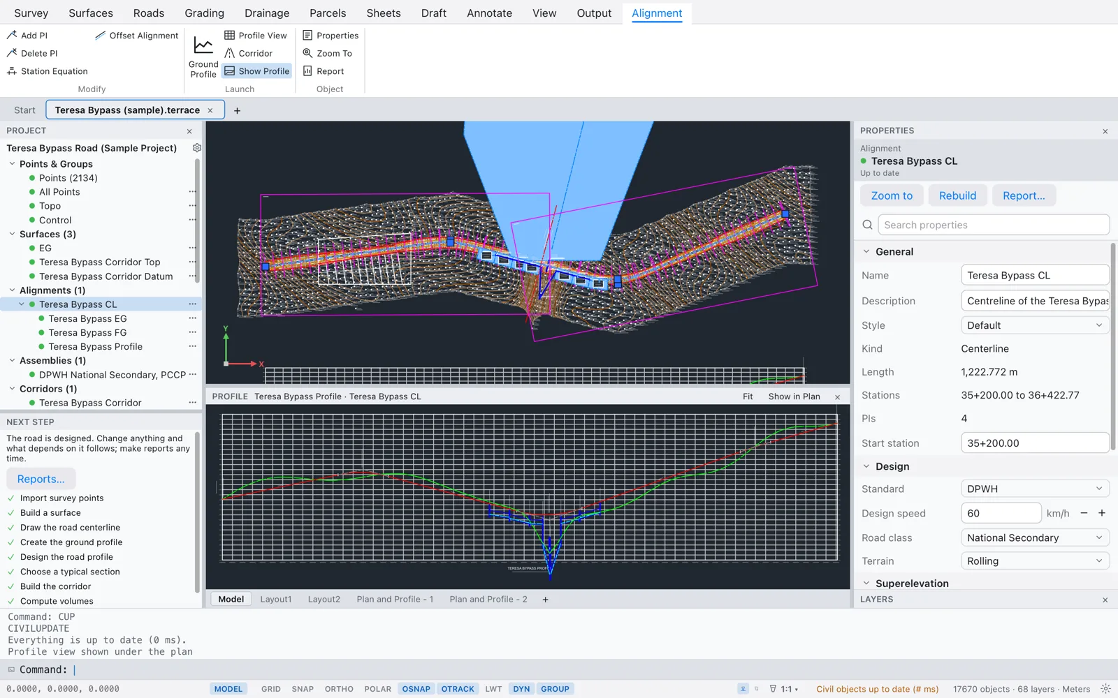
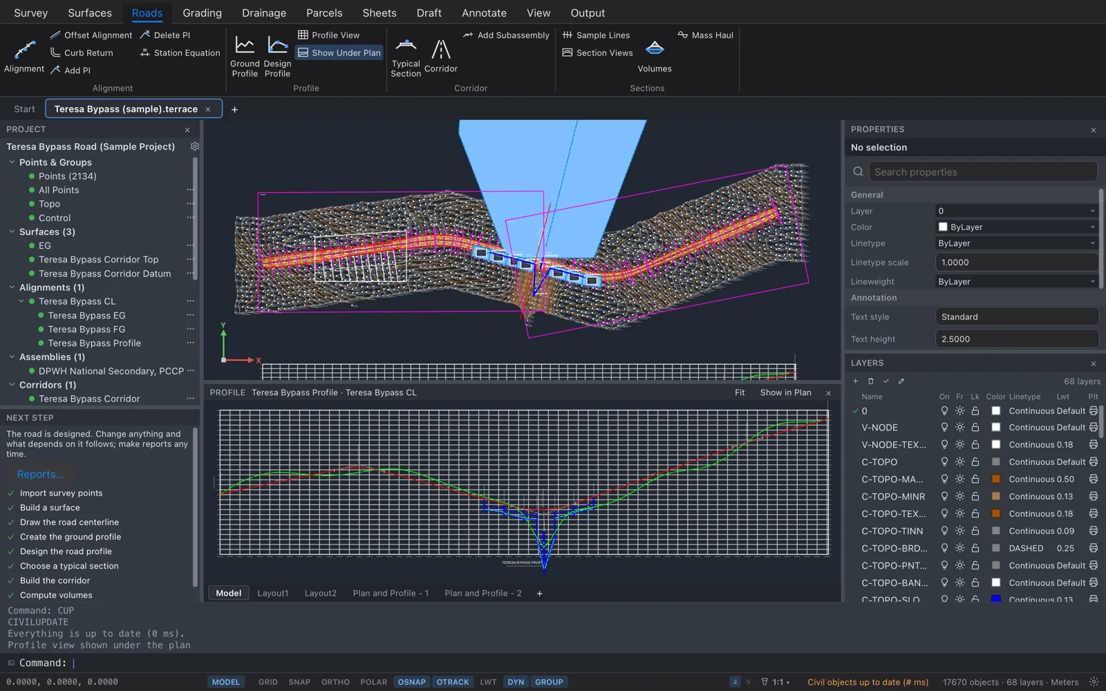
Terrace is laid out around the job, not around drawing tools. From top to bottom:
| Part | Where | What it's for |
|---|---|---|
| Ribbon | Top | One tab per part of the job, then the drafting tabs. Every tool is a button. |
| Drawing tabs | Under the ribbon | Start, then each open project or drawing, then +. |
| Project browser | Left, top | Every civil object in the project, by kind, with a status dot. |
| Next step | Left, bottom | The road workflow: what's done and what to do next, as buttons. |
| Plan | Middle | The drawing itself (model space), where you click, select and edit. |
| Profile pane | Under the plan, when shown | The current alignment's profile view, side by side with the plan. |
| Properties and Layers | Right | The selected object's fields; the drawing's layers. |
| Undo history | Right, when shown | Every step you've made; click one to go back to it. |
| Command line | Bottom | Type commands and answer prompts, as in AutoCAD. |
| Status bar | Very bottom | Cursor coordinates, drafting toggles, the last civil update. |
On a Mac, the menu bar is at the top of the screen as usual: Terrace, File, Edit, View, Insert, Format, Tools, Draw, Dimension, Modify, Window and Help. Three things over the window can appear on top of all this: the command palette (⌘K), the civil dialogs, and the tutorial card.
The ribbon
The ribbon's tabs follow the order a project is made in: Survey, Surfaces, Roads, Grading, Drainage, Parcels, Sheets. After them come the drafting tabs Draft, Annotate, View, Output, Terrace's 2D CAD side. Click a tab's name to show it.
Most buttons start their command just as typing its name would. The buttons that create a civil object open its dialog instead, with everything filled in from the project and the standard: check the fields and click Create. Dialogs that work on an alignment open on the selected one (or the one the selected profile or profile view belongs to, else the one in the profile pane). Hover a button to see the command's title and its short alias (for example Create Alignment · CALIGN); typed, that command asks its questions on the command line instead, and offers Dialog at its first prompt. Big buttons are the main tool of a group; small ones sit three to a column. A small button with a tinted background is a switch that's on (like Show Under Plan).
Tip With no project open, a civil button first makes a new project (with the standard you used last), then opens its dialog or starts its command. You never have to hunt for "New" first.
The buttons that open a dialog:
| Button | Dialog | To do it by clicking instead |
|---|---|---|
| Survey ▸ Point Group | New Point Group | — |
| Surfaces ▸ Create Surface | New Surface | — |
| Roads ▸ Alignment | New Alignment (from a selected polyline) | Click PIs… (CREATEALIGNMENT) |
| Roads ▸ Ground Profile | Ground Profile | — |
| Roads ▸ Design Profile | Design Profile | Click PVIs… (DRAWPROFILE) |
| Roads ▸ Profile View | New Profile View | Place by Clicking… (CREATEPROFILEVIEW) |
| Roads ▸ Typical Section | Typical Section | — |
| Roads ▸ Corridor | New Corridor | — |
| Roads ▸ Sample Lines | Sample Lines | — |
| Grading ▸ Grading | New Grading (for the selected feature line) | — |
| Drainage ▸ Pipe Network | New Pipe Network | Lay Out by Clicking… (CREATENETWORK) |
| Parcels ▸ Parcels | Parcels from Polylines (from selected polylines) | Pick Polylines… (CREATEPARCELS) |
| Sheets ▸ View Frames | Plan and Profile Sheets | — |
The same dialogs open from the contextual tabs and from Next step. Each chapter describes its dialogs; Your first road walks through most of them.
Survey

Points: Import Points, Create Points, Point Group (a dialog), Description Keys, Export Points. Survey Data: Import Raw File, Traverse, Least Squares. Import: LandXML, GIS Data, Point Cloud, Elevation Grid. Project: Coordinate System, Project Settings, Design Standards. See Survey and points and Importing and exporting.
Surfaces

Create: Create Surface (a dialog), From Point Cloud, From Elevation Grid. Add Data: Breaklines, Boundary, Contours. Edit: Edit Surface. Analyze: Volume, Surface Report. See Surfaces.
Roads

Alignment: Alignment (a dialog), Offset Alignment, Curb Return, Add PI, Delete PI, Station Equation. Profile: Ground Profile, Design Profile, Profile View (all three dialogs), Show Under Plan. Corridor: Typical Section, Corridor (dialogs), Add Subassembly. Sections: Sample Lines (a dialog), Section Views, Volumes, Mass Haul. See Alignments, Profiles, Typical sections and corridors and Sections and earthwork.
Grading

Feature Lines: Feature Line, Set Elevation, Set Grade, From Surface, Raise/Lower, Insert Elevation Point. Grading: Grading (a dialog), Balance Cut & Fill. See Grading.
Drainage

Pipe Network: Pipe Network (a dialog), Lay Out Pipes, Design Pipes. Catchments: Catchment. Pressure: Pressure Network. See Drainage and water.
Parcels

Create: Parcels (a dialog), Right of Way. Edit: Subdivide, Slide Line, Swing Line, Renumber. Descriptions: Technical Description. See Parcels.
Sheets

Plan Production: View Frames (a dialog), Plan & Profile Sheets, Section Sheets. Reports: Reports, Stakeout, Earthwork. Export: LandXML, GIS Data, Google Earth, DWG / DXF (Save As). Project: Update Now (CIVILUPDATE), Styles (for the selected civil object when there is one, so the dialog offers to use a style for it), Project Settings. See Sheets and plotting, Reports and Importing and exporting.
Draft, Annotate, View and Output
The drafting tabs hold Terrace's full 2D CAD tools, covered in Drafting. Two of them have parts every Terrace user needs:




Contextual tabs
When you select exactly one alignment, profile (or profile view), corridor or surface, a tab for it appears at the end of the ribbon and is selected: Alignment, Profile, Corridor or Surface. It has the commands that work on that object. When the selection ends, the tab goes away and the tab you were on comes back.

| Tab | Shown for | Buttons |
|---|---|---|
| Alignment | An alignment | Modify: Add PI, Delete PI, Station Equation, Offset Alignment. Launch: Ground Profile, Profile View, Corridor (dialogs, for this alignment), Show Profile. |
| Profile | A profile or profile view | Modify: Design Profile, Profile View (dialogs, for the profile's alignment), Show Under Plan. |
| Corridor | A corridor | Modify: Rebuild, Sample Lines (a dialog, for the corridor's alignment), Volumes. |
| Surface | A surface | Modify: Edit Surface, Breaklines, Boundary, Volume. |
Every contextual tab ends with an Object group: Properties (shows the Properties panel), Zoom To (zooms the plan to the object) and Report (opens the report dialog for it).

The drawing tabs
Under the ribbon is a row of tabs: Start (the start page), one tab for each open project or drawing, and +, which makes a new project. A * after a name means it has unsaved changes. Click × on a tab to close it; Terrace asks Save changes to …? if there's anything unsaved.
If you've closed the Project panel, a Project ▸ link at the right end of this row brings it back.
The Project browser
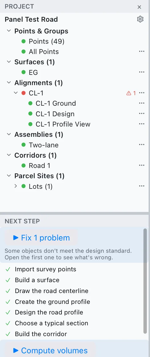
The Project panel's top half lists every civil object in the project, so you never have to hunt for something in the plan. At the top is the project's name (from Project Settings, or the file name), with a gear that opens Project Settings.
Objects are grouped by kind, in the order you make them: Points & Groups, Surfaces, Alignments (with each alignment's profiles and profile views under it), Assemblies, Corridors, Sample Line Groups, Feature Lines & Gradings, Pipe Networks, Catchments, Pressure Networks, Parcel Sites (with their parcels under them) and View Frame Groups. A heading only appears once the project has an object of that kind; it shows how many there are.
- Click the arrow (or a heading's name) to open or close a group. Alignments start open; parcel sites start closed.
- Click an object to select it in the plan and show it in Properties.
- Double-click an object to zoom the plan to it.
Status dots
Each object has a coloured dot. Hover it to read what it means.
| Dot | Meaning |
|---|---|
| ● Green | Up to date. |
| ● Amber | Waiting for a rebuild: it's older than what it's built from, because it's locked or set to rebuild by hand. Rebuild it from its menu or with CIVILREBUILD. |
| ● Red | Has problems: it doesn't meet the design standard. A ⚠ and the number of problems show at the end of its row. |
A closed alignment shows its profiles' problems on its own dot, so nothing hides inside a closed group.
The object menu
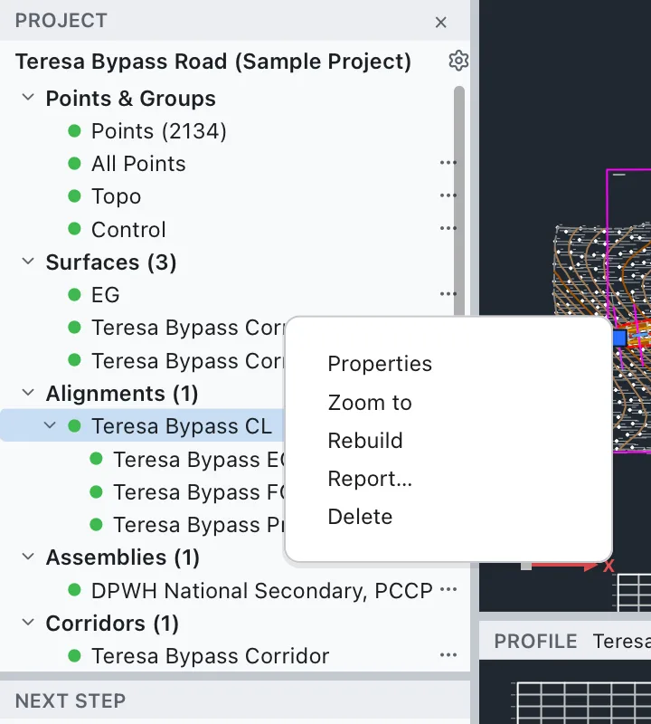
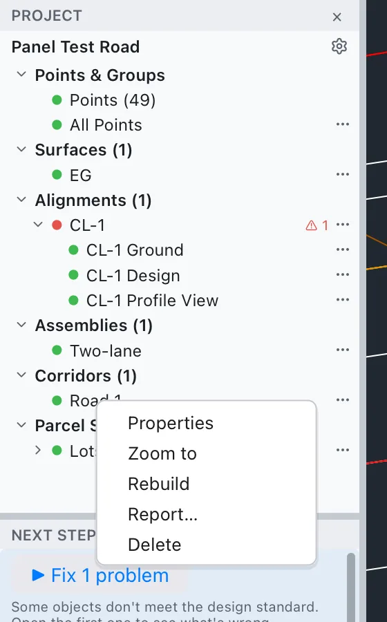
Each object has a small menu: right-click its row, or click the ⋯ at the end of it.
| Item | What it does |
|---|---|
| Properties | Selects the object and shows the Properties panel (opening it if it was closed). |
| Zoom to | Zooms the plan to the object. If it has nothing drawn yet, the command line says so. |
| Rebuild | Rebuilds the object and what depends on it now, even if it's locked or rebuilds by hand. One undo step; the command line says how many objects were rebuilt and how long it took. |
| Report… | Opens the report dialog for the object. |
| Delete | Deletes the object. If other objects use it, Terrace first asks Delete …?, naming them; Delete All deletes them too. One undo step, so ⌘Z brings everything back. |
Points and parcels have a shorter menu: Properties, Zoom to and Report… (right-click only; they have no ⋯).
Next step
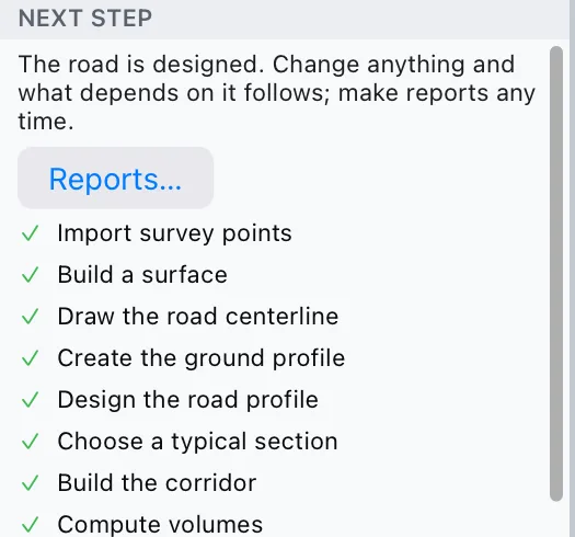
The bottom half of the Project panel, NEXT STEP, works out from the project what you've done and what comes next on a road job. It's a checklist and a launcher in one.
- Done steps have a green ✓.
- The next step is a button (▶ Build a surface) with one line under it saying why it matters. Click it to open the step's dialog (or start its command).
- Later steps are dimmed, but still work when clicked; hover one to read why.
- When objects don't meet the standard, ▶ Fix N problems comes first. Clicking it selects the first object with a problem, shows its Properties, and zooms the plan to the place.
The steps and what each starts:
| Step | Opens | Ticked when |
|---|---|---|
| Import survey points | IMPORTPOINTS (asks for the file, then shows the import dialog) | The project has points or a surface |
| Build a surface | The New Surface dialog | There's a surface |
| Draw the road centerline | The New Alignment dialog | There's a centerline alignment |
| Create the ground profile | The Ground Profile dialog | There's a profile from a surface |
| Design the road profile | The Design Profile dialog | There's a design (layout) profile |
| Choose a typical section | The Typical Section dialog | There's an assembly |
| Build the corridor | The New Corridor dialog | There's a corridor |
| Compute volumes | The Sample Lines dialog (it computes the volumes too); COMPUTEVOLUMES once sample lines exist | Volumes are computed |
| Make plan & profile sheets | The Plan and Profile Sheets dialog; CREATESHEETS once view frames exist | A view frame group has frames |
When every step is ticked, the panel says The road is designed. and offers a Reports… button.
The plan
The plan in the middle is the drawing (model space), with a dark background like most CAD programs. Civil objects draw here as ordinary lines, arcs, text and hatches, on layers named after the U.S. National CAD Standard (C-ROAD-CNTR for centerlines, C-TOPO-MAJR for major contours…). You can't edit those graphics directly: they're redrawn from their object. See Selecting and editing.
- Zoom with the scroll wheel or a pinch; pan with a drag of the middle button, or by holding Space and dragging. (In Options you can make two-finger scrolling pan instead of zoom.)
- View ▸ Extents (or
ZOOME) fits the whole drawing. - Under the plan are the layout tabs: Model, then each layout (sheets are layouts) and +. See Sheets and plotting.
The profile pane under the plan
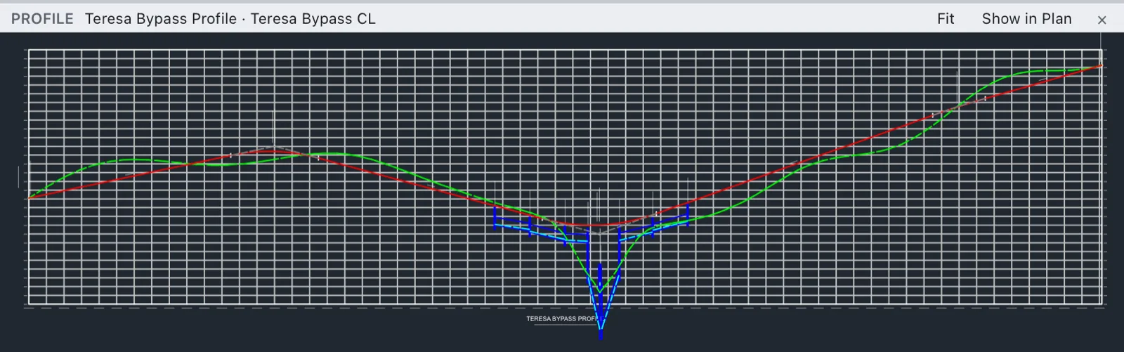
While you work on a road, you often want the plan and the profile side by side. The profile pane splits the plan and shows the profile view of the current alignment below it.
- Click Roads ▸ Show Under Plan (also on the Alignment and Profile contextual tabs, View ▸ Profile View in the ribbon, and View ▸ Profile View Under Plan in the menu bar).
- The pane opens with the profile view fitted. Its header names the view and the alignment: PROFILE Teresa Bypass Profile · Teresa Bypass CL.
- Which alignment? The one you last selected — or whose profile, profile view or corridor you selected. Before you've picked one, it's the project's first alignment.
- In the pane, the scroll wheel zooms and a drag pans. A double-click centres the plan on the point you clicked.
- Fit fits the profile view again; Show in Plan zooms the plan to the profile view, where you can drag its PVI grips; × closes the pane.
- Drag the bar between the plan and the pane to share the height.
- If the alignment has no profile view yet, the pane says so and offers a Create Profile View button. With no alignment at all, it tells you to draw the centerline first.
Properties
The Properties panel on the right changes with what's selected.
For a civil object
Select a civil object (in the plan or the browser) and Properties shows one plain panel for it:
- A heading with the kind (Alignment), the name, the status dot and its words (Up to date).
- Buttons: Zoom to, Rebuild and Report….
- Its problems in plain words, each with Zoom to; and notes from its last build.
- A search box, then its fields in groups (General, Design, Superelevation…). Number fields know their units (km/h) and have − / + steppers.
Every change you make in a field is one undo step, and everything that depends on the object follows at once. If a value can't be used, the panel says why in red and leaves the object as it was. Each kind's fields are described in its own chapter.
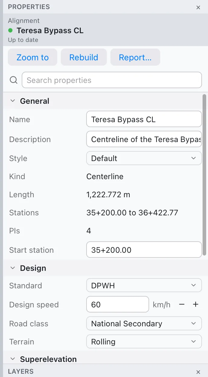
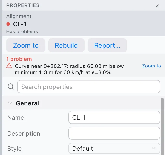
While a civil object's panel is shown, the Layers panel below it folds to its header to give Properties the height; it opens again when the selection is plain drawing.
For drawing objects
With nothing selected, or with plain drawing objects (lines, text…) selected, Properties shows the drawing properties you know from CAD: General (Layer, Color, Linetype, Linetype scale, Lineweight), Annotation and the rows of the selected objects. See Drafting.
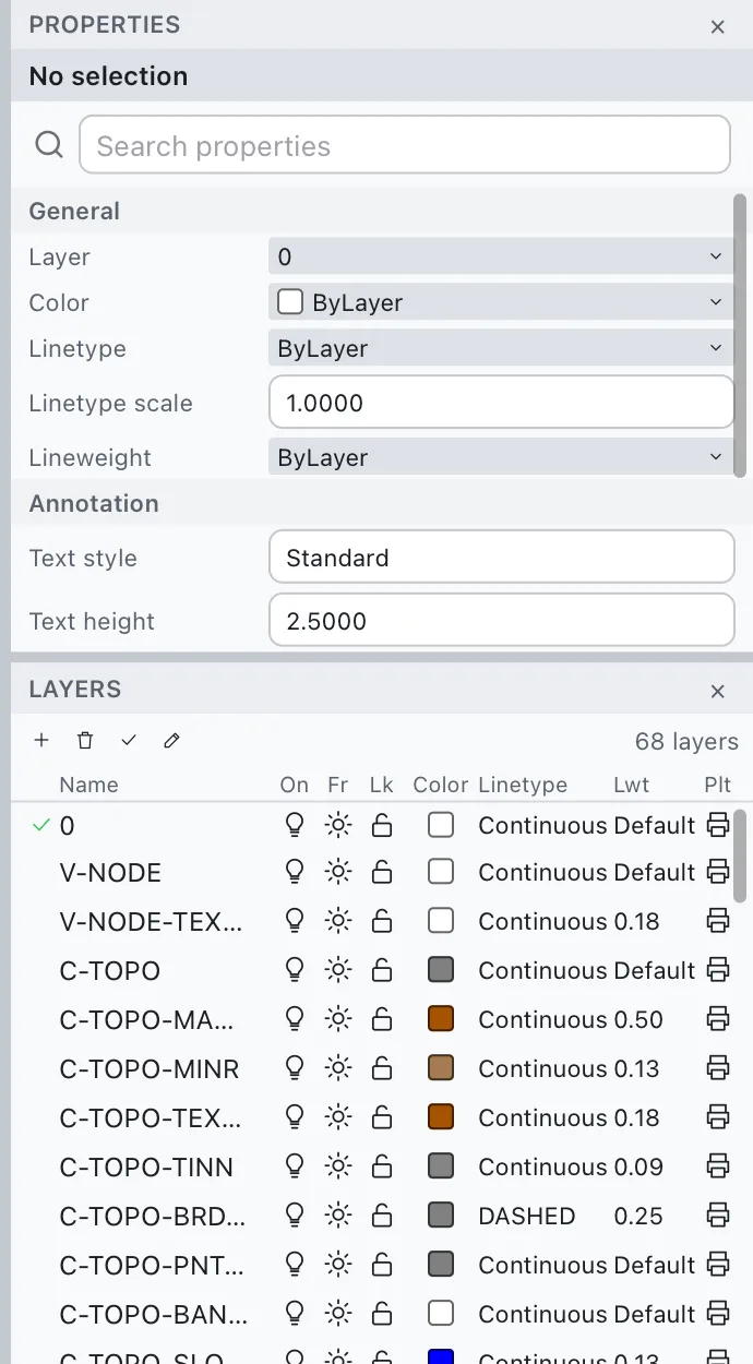
Layers
The Layers panel lists the drawing's layers with switches for on/off, freeze, lock, colour, linetype, lineweight and plotting, and buttons to add, delete, set current and rename. Civil objects draw on their own layers, so this is where you hide, say, the point labels (V-* layers in the sample) or the contours. Drag the bar between Properties and Layers to share the height. See Drafting for everything the panel does, and Standards and styles for which layers civil objects use.
The undo history
The undo history is a panel listing every step you've made in the drawing, named after the command or change (Grip Edit, Project Settings…). Show it with View ▸ Undo History in the menu bar or the ribbon's View tab. It appears at the bottom of the right side. Click any row to go straight back (or forward) to just after that step. See The visual undo history.
The command line
At the bottom of the window, as in AutoCAD, is the command line: the last few lines of what happened, and the prompt (Command:) with what you type. You don't need to click it: just type, from anywhere, and press Enter or Space. Every civil tool has a command name and short aliases. Press F2 to see more lines. See The command line and aliases.
The status bar

The status bar is the strip along the very bottom of the window. From left to right:
- The cursor's coordinates (X, Y, Z) in the drawing's units, snapped while a command wants a point.
- MODEL / PAPER: click it to go from the plan to the last layout and back (in a layout, it switches between paper space and the viewport's model space).
- The drafting toggles: GRID, SNAP, ORTHO, POLAR, OSNAP, OTRACK, LWT, DYN and GROUP. Click one to switch it; highlighted ones are on. (F3 OSNAP, F7 grid, F8 ortho, F9 snap, F10 polar, F11 object tracking, F12 dynamic input.)
On the right:
- In a layout with a viewport selected, that viewport's scale (click to choose another) and a button to maximize it.
- Two small switches for annotative objects (show them at every scale; add scales as the annotation scale changes) and the annotation scale of the current view, 1:1 ▾; click it to choose another.
- The last civil update, once something has changed: for example Civil objects up to date (12 ms) or Updated 5 objects, redrew 5 in 31 ms. It turns orange when there's more to read; hover it to see every line, including any objects Waiting for a rebuild.
- While a big file opens in the background (or the sample project is being built), what's going on, in orange: Opening ….
- The drawing's object and layer counts and units (17670 objects · 68 layers · Meters), and a gear for Drafting Settings.
Showing, hiding and resizing panels
Every panel can be closed with the × in its header and brought back from the View tab's Panels group or the View menu. Terrace remembers the layout for next time.
| Panel | Show / hide | Resize |
|---|---|---|
| Project (browser + Next step) | View ▸ Project (ribbon), View ▸ Project Panel (menu), or Project ▸ in the drawing tabs row | Drag its right edge (180–560 points wide); drag the bar above NEXT STEP to share the height |
| Profile pane | Roads ▸ Show Under Plan, View ▸ Profile View | Drag the bar above it |
| Properties | View ▸ Properties, ⌘1 | Drag the right side's left edge (200–640 points) |
| Layers | View ▸ Layers, Format ▸ Layer… | Drag the bar between Properties and Layers |
| Undo history | View ▸ Undo History | Shares the right side |
| Command history | F2, View ▸ History | — |
Light and dark
Terrace follows your system's appearance: light chrome in light mode, dark in dark mode. The plan keeps its dark CAD background either way unless you change it.
To choose for yourself, open Terrace ▸ Settings… (⌘,) or Output ▸ Options:
- Appearance: System, Light or Dark. The window changes when Terrace starts again.
- Model space background: Dark background, Light background or Follow theme, with the colours as hex RGB and presets (Dark, Black, Gray, White). On a light background, black-and-white objects (colour 7) turn black.
The rest of the Options dialog is described in Projects and files and Drafting.