
Alignments
This chapter shows how to draw a road centerline in Terrace, with its curves and spirals, stations, offset edges and curb returns, and how Terrace works out the superelevation and checks the design against the standard. When you finish it you'll be able to lay out an alignment, change it, read its problems and print its geometry, stakeout and superelevation reports.
Alignments, PIs, curves and spirals
An alignment is the line a road follows on the plan, usually its centerline. Everything else in the road hangs on it: the ground and design profiles, the corridor, the sample lines, the plan-and-profile sheets.
You draw an alignment the way a highway engineer lays one out on a map: by its PIs (points of intersection), the corners where two straight tangents meet. Terrace puts a curve of a given radius at every inside PI, so the road turns smoothly instead of at a corner.
A spiral (clothoid, or transition curve) is a curve whose radius changes steadily from straight to the circular radius. It sits between the tangent and the circular curve on each side, so a driver turns the wheel gradually and the road has room to tilt into its superelevation. Terrace labels the points along a curve the usual way: TS (tangent to spiral), SC (spiral to curve), CS (curve to spiral) and ST (spiral to tangent), or PC and PT for curves without spirals.
Along the alignment, distances are stations, written kilometres + metres: 35+200.00 is 35.2 km from the start of the stationing. The sample project's Teresa Bypass Road starts at Km 35+200.
The Roads tab
Every alignment tool is in the Alignment group of the Roads ribbon tab. When an alignment is selected, a contextual Alignment tab appears as well, with the editing tools, the next steps (Ground Profile, Profile View, Corridor, Show Profile) and the Properties, Zoom To and Report buttons.
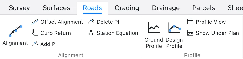
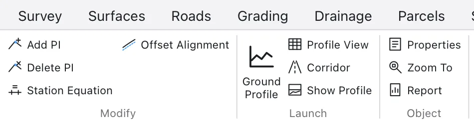
| Button | Command (aliases) | What it does |
|---|---|---|
| Alignment | CREATEALIGNMENT (CALIGN, ALIGNMENT) | Opens the New Alignment dialog: a centerline from the selected polyline, or Click PIs… to draw it |
| Offset Alignment | OFFSETALIGNMENT (OALIGN) | Edges offset left, right or both sides |
| Curb Return | CURBRETURN (CRETURN) | A return arc in the corner of two crossing roads |
| Add PI | ADDPI (INSERTPI) | Inserts PIs where you click |
| Delete PI | DELETEPI (REMOVEPI) | Removes the PIs you click |
| Station Equation | STATIONEQUATION (STAEQ) | A break in the stationing (back = ahead) |
The full list of Roads commands is in the command reference.
Drawing the centerline by clicking PIs
This is the usual way to start a road: you click the PIs on the plan, over your surface or a background map, and Terrace fits the curves for you as you go.
- Type
CREATEALIGNMENT(CALIGN) and press Enter. Or click Roads ▸ Alignment (or Draw the road centerline in the Next step panel): the New Alignment dialog opens; click Click PIs… at its bottom left and it closes and starts the same command. - Read the first line Terrace writes: it tells you the defaults it picked (see below). Change any of them now with the options on the prompt, or keep them.
- Click the start point, then click each PI in turn. A live preview follows the cursor: the tangents as a light line and the solved alignment with its curves and spirals.
- Press Enter after the last point to finish. You need at least two points.

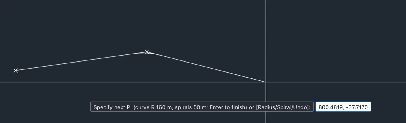
While you place PIs, the prompt offers:
| Option | What it does |
|---|---|
| Radius | The curve radius for the PIs you place next. The prompt shows the standard's minimum for the design speed. Type 0 for no curve (an angle point). If you type a radius below the minimum, Terrace accepts it and writes a note. Unless you set the spiral yourself, the spiral length follows the new radius. |
| Spiral | The spiral length on both sides of the next curves. Type 0 for simple circular curves. |
| Undo | Takes the last PI back. With only the start point left, it goes back to the start prompt. |
Each PI keeps the radius and spiral that were set when you clicked it. To give one PI a sharper curve, choose Radius, type it, click that PI, then set the radius back.
Tip You can type coordinates instead of clicking. With dynamic input on (DYN in the status bar), the second and later points you type are relative to the last one, as in AutoCAD. Type # in front for absolute coordinates: #420,60.
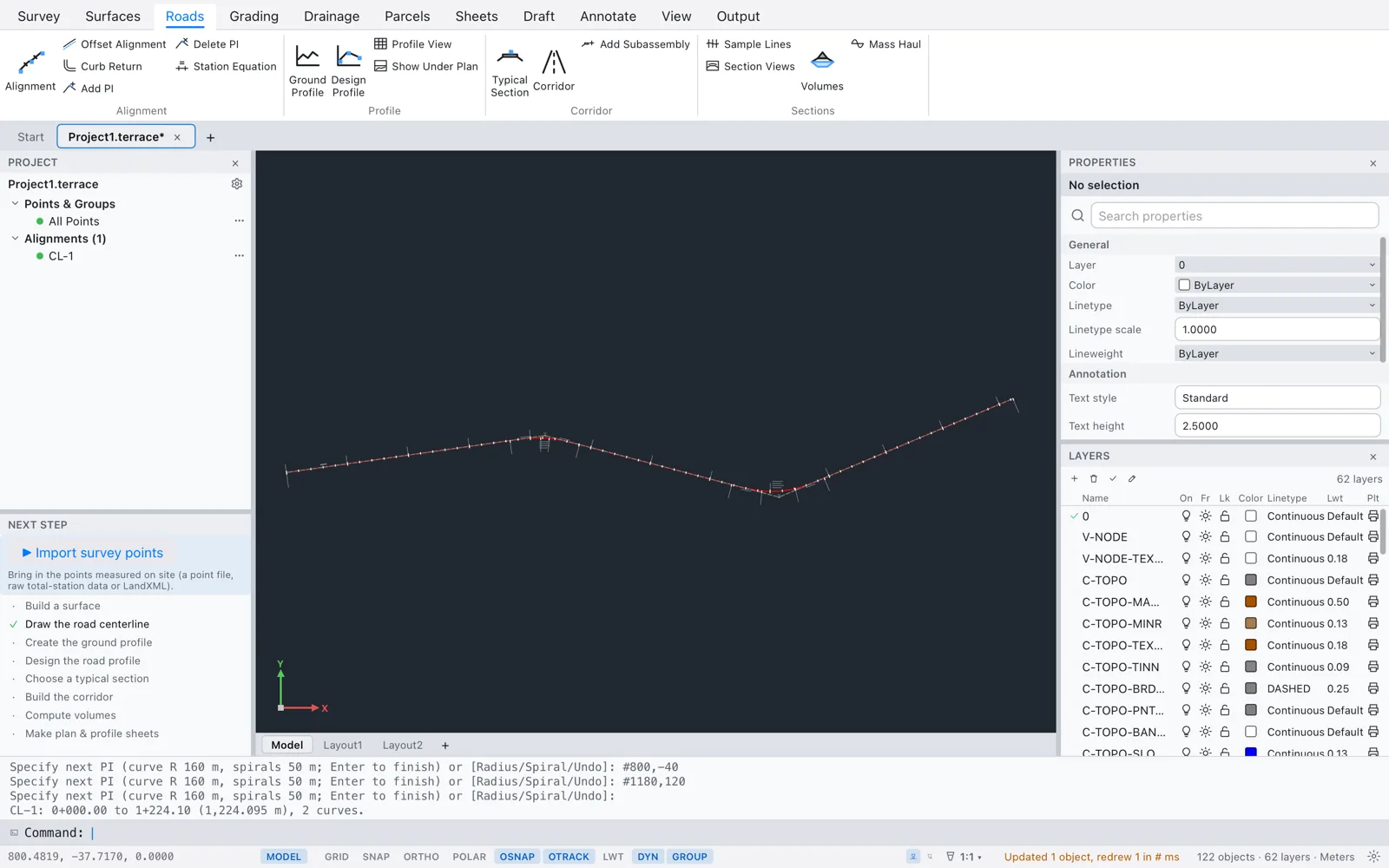
When you finish, Terrace adds the alignment, checks it against the standard and writes a summary, for example CL-1: 0+000.00 to 1+224.10 (1,224.095 m), 2 curves. Any problems are listed under it (see Design checks). The alignment appears in the Project browser under Alignments, with stations, curve data and PI labels drawn on the plan.
The defaults Terrace picks
You don't need to look anything up before drawing. CREATEALIGNMENT takes its design values from the project's standard (DPWH unless you chose AASHTO):
- Road class: the class of the last alignment you drew, or National Secondary in a DPWH project (Rural Collector in AASHTO).
- Terrain: rolling.
- Design speed: the class's speed for the terrain. National Secondary is 80 km/h on level ground, 60 km/h rolling and 50 km/h mountainous, so a new DPWH road starts at 60 km/h.
- Maximum superelevation (e max): the highest rate in the standard's tables, 10 % for DPWH.
- Curve radius: 1.5 times the minimum radius for the speed at that e max, rounded up to 10 m (50 ft in US projects). At 60 km/h that is 160 m.
- Spiral length: the standard's spiral length for the speed, or the superelevation runoff length when that is longer, rounded up to 5 m (10 ft). At 60 km/h with R = 160 m that is 50 m.
- Name: CL-1, CL-2 and so on.
To change them, choose an option at the first prompt, before you click the start point:
| Option | What it does |
|---|---|
| Name | The alignment's name. It must not be taken. |
| Speed | A design speed of your own. The radius and spiral defaults follow it. |
| Class | A road class of the standard. Terrace lists them; type the first letters (National T for National Tertiary). The speed follows the class. |
| Terrain | Level, Rolling or Mountainous. The speed follows the terrain. |
| Polyline | Makes the alignment from a polyline (next section). |
| Dialog | Type D: the command ends and the New Alignment dialog opens instead. |
The new alignment gets superelevation turned on, with the e max above and the normal crown and lane width of its road class (1.5 % and 3.35 m for National Secondary). In a US-feet project its stations are labelled every 100 ft with ticks every 50 ft. You can change all of these later in Properties.
Making an alignment from a polyline
If the route is already drawn, for example a centerline from an old plan or a DXF, turn it into an alignment instead of clicking it again. You can do it with the New Alignment dialog or with the command.
The New Alignment dialog
- Select the polyline: click it in the drawing. (If you select several, the dialog uses the first.)
- Click Roads ▸ Alignment, or Draw the road centerline in the Next step panel. The New Alignment dialog opens with every field filled in, and says From the selected polyline.
- Change what you need and click Create.
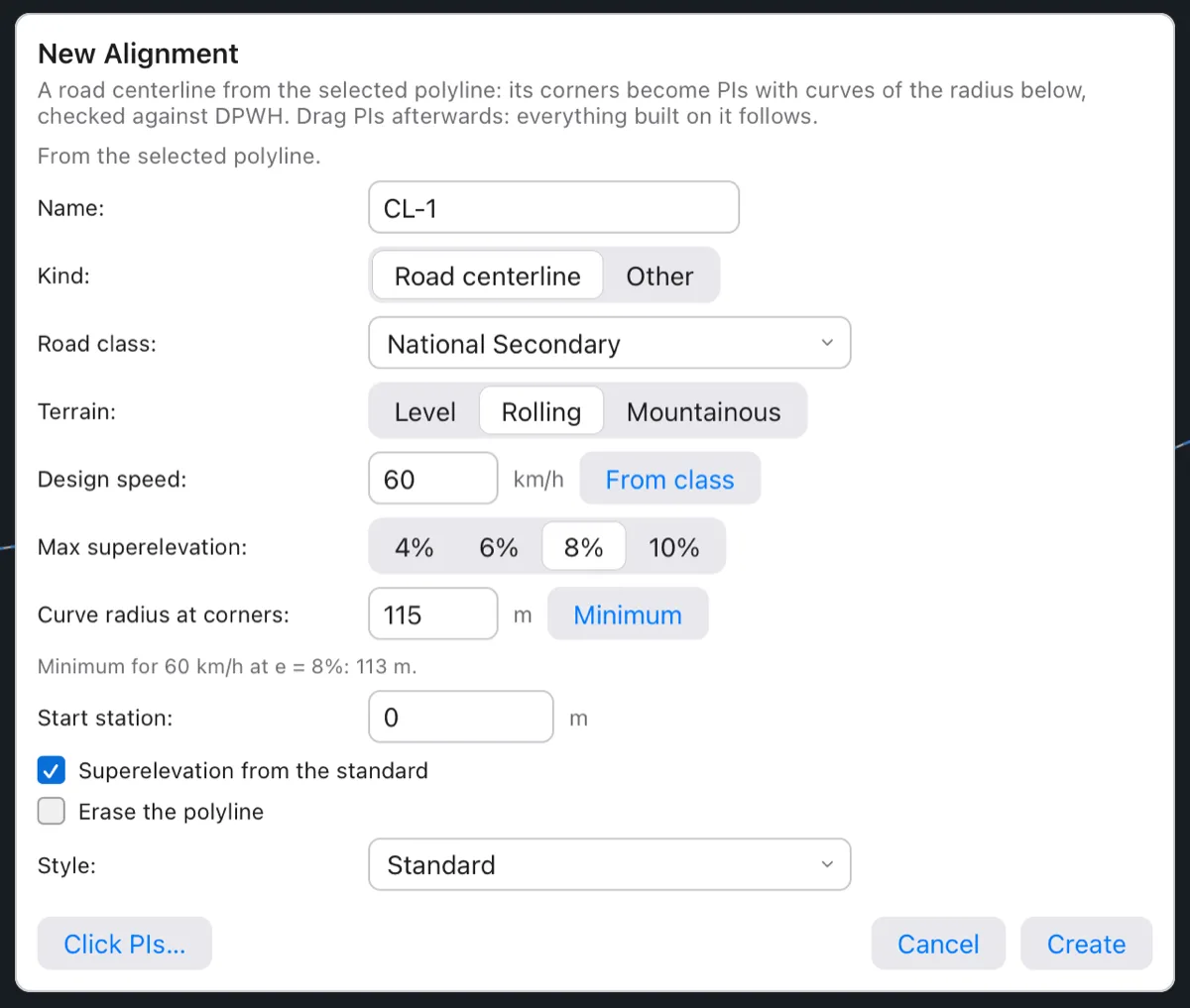
| Field | Default | What it does |
|---|---|---|
| Name | CL-1, CL-2… | Must not be taken. |
| Kind | Road centerline | Other makes a miscellaneous alignment (a ditch, a fence line…). |
| Road class | The class of the project's alignments; in a new project, the class whose rolling-terrain speed is nearest 60 km/h (National Secondary for DPWH) | A class of the standard. It sets the lane width and normal crown used by the superelevation. |
| Terrain | Rolling | Level, Rolling or Mountainous. |
| Design speed | The class's speed for the terrain (60 km/h) | From class puts back the class's speed after you change the class or terrain, and recomputes the radius. |
| Max superelevation | 8 % (the highest rate of the standard's tables up to 8 %) | e max: 4, 6, 8 or 10 % for DPWH. |
| Curve radius at corners | The standard's minimum radius for the speed and e max, rounded up to 5 m (50 ft): 115 m at 60 km/h and 8 % | The radius given to every corner of the polyline that has no arc. Minimum puts back the default; the line under it shows the exact minimum. |
| Start station | 0 | The station of the first point (type 35200 for 35+200). |
| Superelevation from the standard | On | Turns superelevation on with the e max above and the class's lane width and normal crown. |
| Erase the polyline | Off | Removes the polyline once the alignment is made. |
| Style | Standard | How the alignment is drawn. |
Each polyline vertex becomes a PI. Arcs in the polyline stay as curves; every other corner gets a simple circular curve of the radius above (the dialog adds no spirals). Terrace checks the alignment and writes, for example, Alignment CL-1 made: 0+000.00 to 1+226.07., with the number of design problems if there are any.
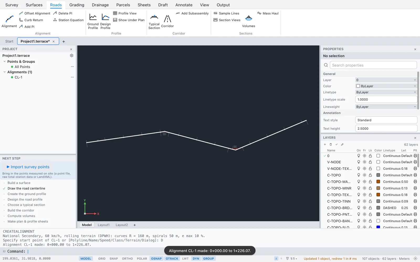
If no polyline is selected, the dialog says so at the top. Select one and open it again, or click Click PIs… to draw the alignment by clicking (it closes the dialog and starts CREATEALIGNMENT, as in Drawing the centerline by clicking PIs).

Note The dialog and the command start from slightly different defaults: the dialog takes e max 8 % and the minimum radius (115 m at 60 km/h), the command e max 10 % and 1.5 times the minimum with spirals (160 m, 50 m spirals). Both meet the standard; pick the one that suits your road.
With the command
- Start
CREATEALIGNMENTand set the name, class, speed or terrain if you want. - Choose Polyline (type
P, Enter). - Click the polyline (a line works too).
Each polyline vertex becomes a PI. Arcs in the polyline stay as curves; every corner without an arc gets the command's default curve and spirals, and Terrace says how many it added (Curves of R = 160 m added at 1 corner). A closed polyline gives a loop that ends where it starts. The polyline itself stays in the drawing; erase it if you no longer need it.
Alignment Properties
Select an alignment (click it on the plan, or click its name in the Project browser) and the Properties panel shows it. At the top are its status (Up to date or Has problems), the buttons Zoom to, Rebuild and Report…, and the list of problems, if any. Every change you make here is one undo step, and everything built on the alignment follows at once.
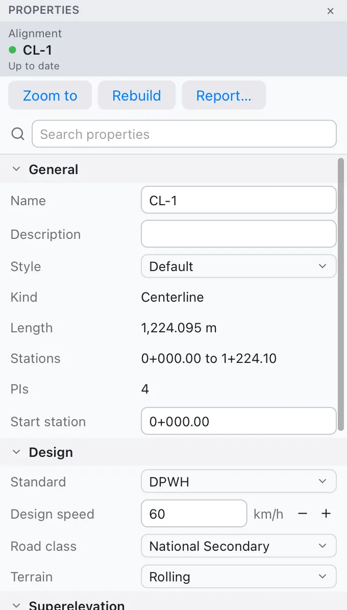
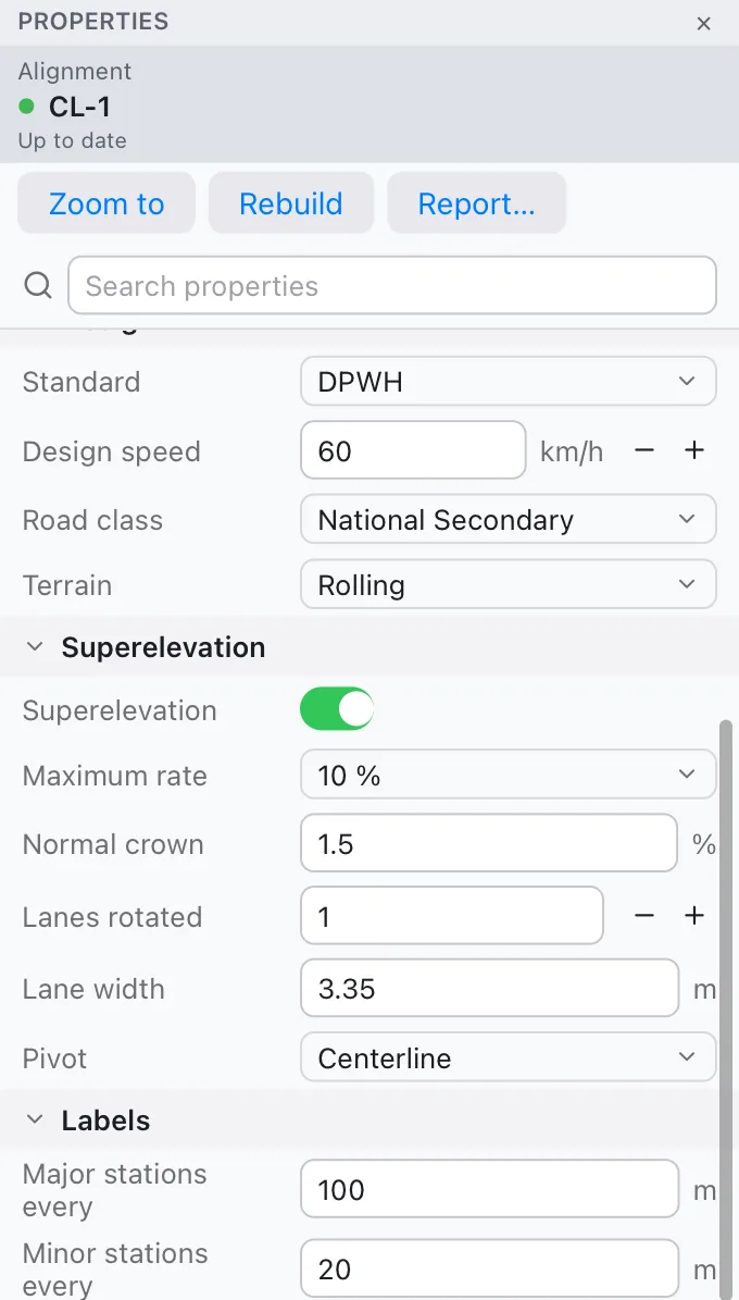
| Group | Row | What it is |
|---|---|---|
| General | Name, Description | Free text. Names must be unique. |
| Style | How it's drawn (see Standards and styles). | |
| Kind | Centerline, Offset, Curb return or Miscellaneous (read only). | |
| Length, Stations, PIs | Read only. | |
| Start station | The station of the first point. Type 35+200 or 35200. | |
| Offset from, Offset | Offset alignments only: the parent and the distance (+ right, − left). | |
| Design | Standard | The design standard of the whole project. Changing it here re-checks every alignment and profile. |
| Design speed | Used by the checks, the superelevation and the profile's K values. | |
| Road class | A class of the standard, or Not set. | |
| Terrain | Level, Rolling, Mountainous or Not set (the profile's maximum grade depends on it). | |
| Superelevation | Superelevation | On or off. The rows below show only when it's on. |
| Maximum rate | e max, from the standard's tables (4, 6, 8 or 10 % for DPWH). | |
| Normal crown | The cross slope on tangents, in %. | |
| Lanes rotated | Lanes tilted on each side, 1 to 4. | |
| Lane width | Used for the runoff length. | |
| Pivot | What the road turns about: Centerline, Inside edge or Outside edge. | |
| Labels | Major stations every | Station labels (100 m by default). |
| Minor stations every | Ticks between them (20 m by default; 0 for none). |
The radius and spirals of each curve aren't in Properties: change them with the curve's grip (next section).
Editing with grips, ADDPI and DELETEPI
Grips
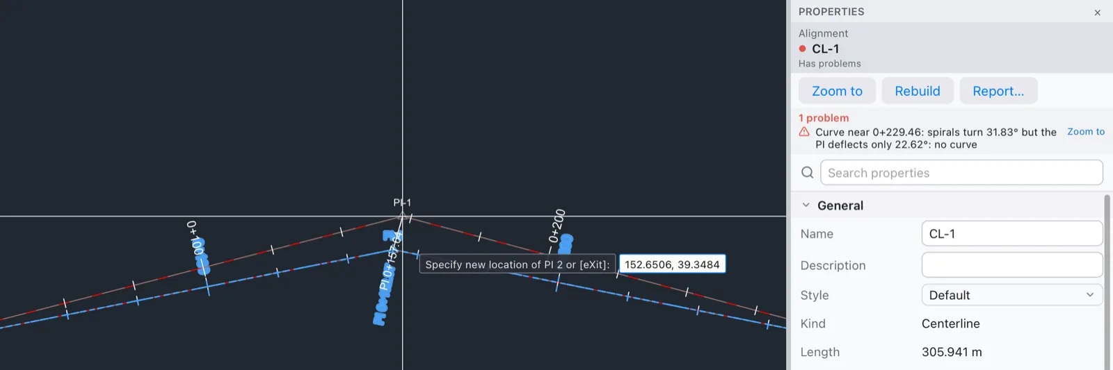
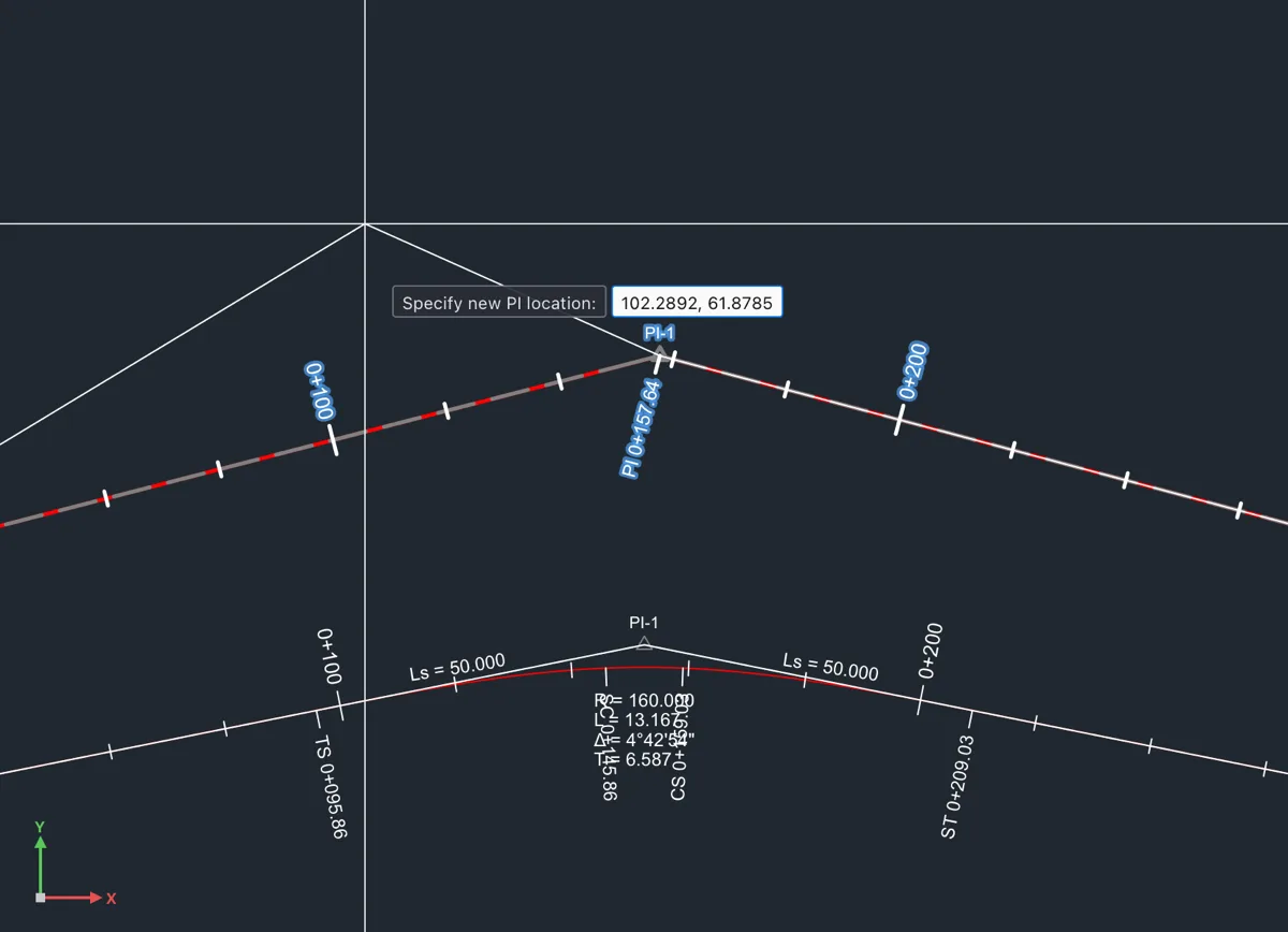
A selected alignment shows two kinds of grips: one at each PI, and one at the middle of each curve, just inside the PI. Dragging them is the quickest way to try an idea, because the alignment, and everything built on it, is solved again as you move.
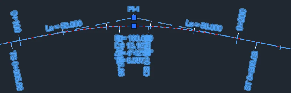
- Select the alignment.
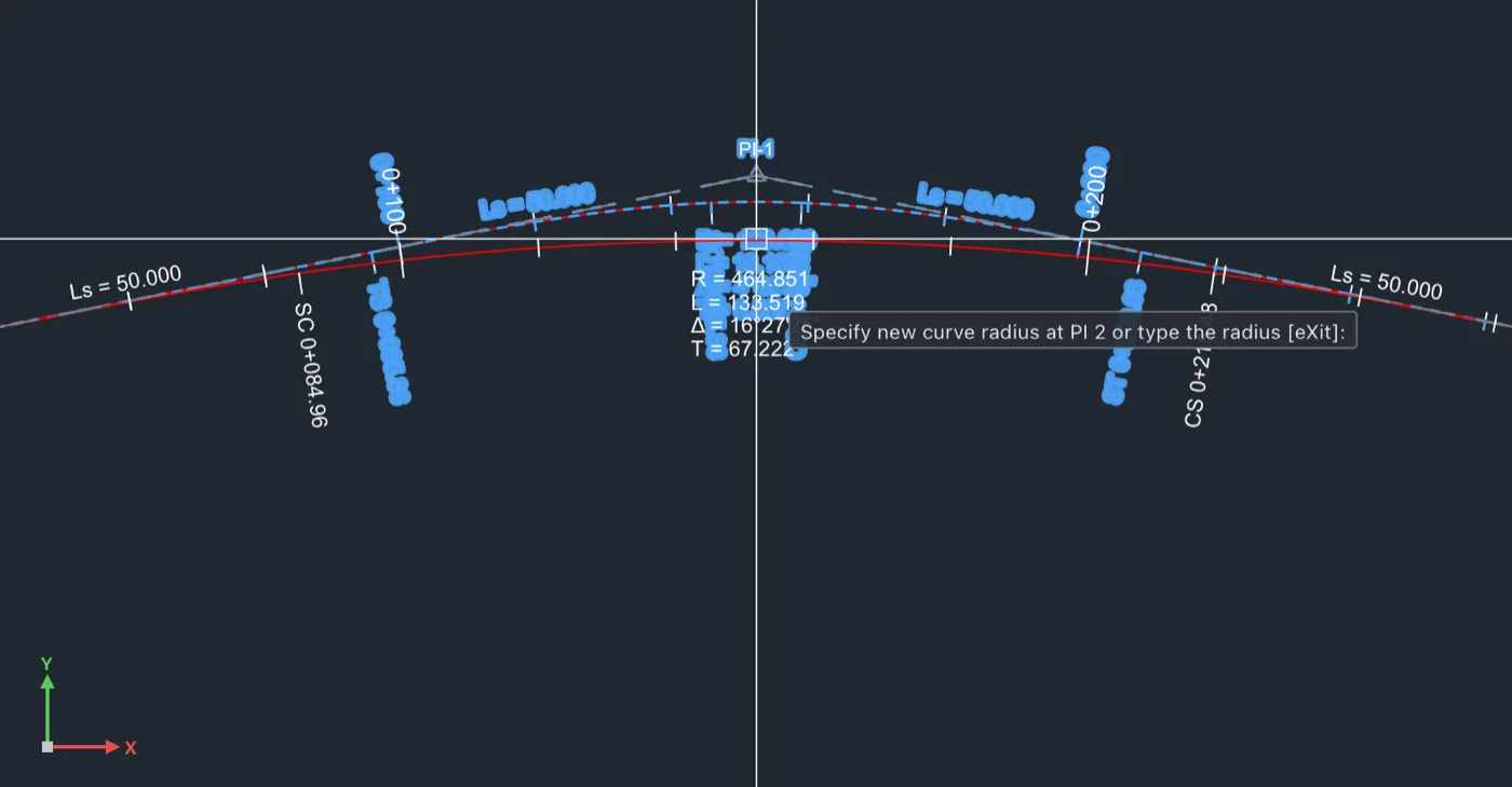
- Click a grip. The command line says which one (
** PI 2 **or** CURVE RADIUS AT PI 2 **). - Move the cursor. The alignment is redrawn live, with its new curve data.
- Click to put the grip down. The change is one undo step (Grip Edit).
The PI grip moves the PI. The radius grip sets the radius from how far you pull the curve's middle from the PI: towards the PI makes it sharper, away makes it flatter. Instead of clicking, you can type the radius and press Enter.
Tip An alignment counts as one object for grips, however many ticks and labels it draws, so a full-length road shows its grips like a short one. Grips are hidden only when more than 100 objects are selected at once.
Adding and deleting PIs
- Click Add PI (
ADDPI) or Delete PI (DELETEPI). - Pick the alignment: click it, type its name, or press Enter for the one shown in angle brackets (the selected or last one).
- For Add PI, click where the new PI goes: the preview shows the alignment with the PI inserted between its nearest neighbours. For Delete PI, click near the PI to remove.
- Keep clicking to add or delete more. Press Enter to stop.
Each click is its own undo step, and Terrace writes how many PIs the alignment has now. An alignment always keeps its two end points. Offset alignments and curb returns don't have PIs of their own: they follow their parent roads.
Stations and station equations
An alignment's stations start at its Start station (Properties), 0+000.00 by default. A road that continues an existing one usually starts at the kilometre post where you join it, like the sample's 35+200.
A station equation is a break in the stationing: from a point on, the stations jump to another value. You need one when a realigned road must keep the stations of the old road beyond the change, or when it meets a kilometre post.
- Click Station Equation (
STATIONEQUATION,STAEQ) and pick the alignment. - Give the back station: type it (
0+500) or click the point on the alignment. - Type the ahead station, the value the stations take from there (
1+000). - Choose whether stations ahead are Increasing (the default) or Decreasing.

Labels, reports, profiles and sections all use the equated stations.
Offset alignments
Offset alignments are lines a fixed distance from a centerline: edges of pavement, shoulders, right-of-way lines. They follow their parent: move a PI of the centerline and the edges move with it.
- Click Offset Alignment (
OFFSETALIGNMENT,OALIGN) and pick the alignment. - Type a distance: positive for the right side, negative for the left. Or choose Both and type one distance for both sides. Pressing Enter takes the default: the road class's lane width on both sides (3.35 m for National Secondary).
The new alignments are named after the parent, side and distance (CL-1 L 3.35 and CL-1 R 3.35), drawn on layer C-ROAD-EDGE, and take the parent's speed, class and stations. To change the distance later, select the offset and edit Offset in Properties.
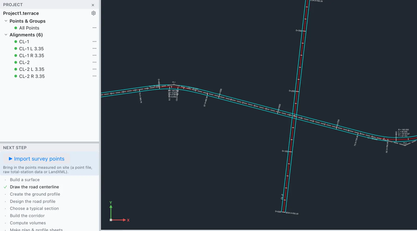
Note Terrace's offset alignments keep one distance along their whole length. The engine can store widenings (stretches where the offset changes, with tapers), but there's no command or Properties row to add one yet. Pavement widening on curves is computed for you and shown in the superelevation report.
Curb returns
Where two roads meet, the edges are joined by a curb return, a circular arc in the corner. Terrace builds it as an alignment of its own, tied to both roads.
- Click Curb Return (
CURBRETURN,CRETURN). - Pick the first road: a centerline or, usually, an edge. Then pick the second road. They must cross; if they don't, Terrace says so and stops.
- Type the radius, or press Enter for the default (10 m, or the last radius you used).
- Move the cursor into the corner you want: the return is previewed in whichever of the four corners the cursor is in. Click to make it.
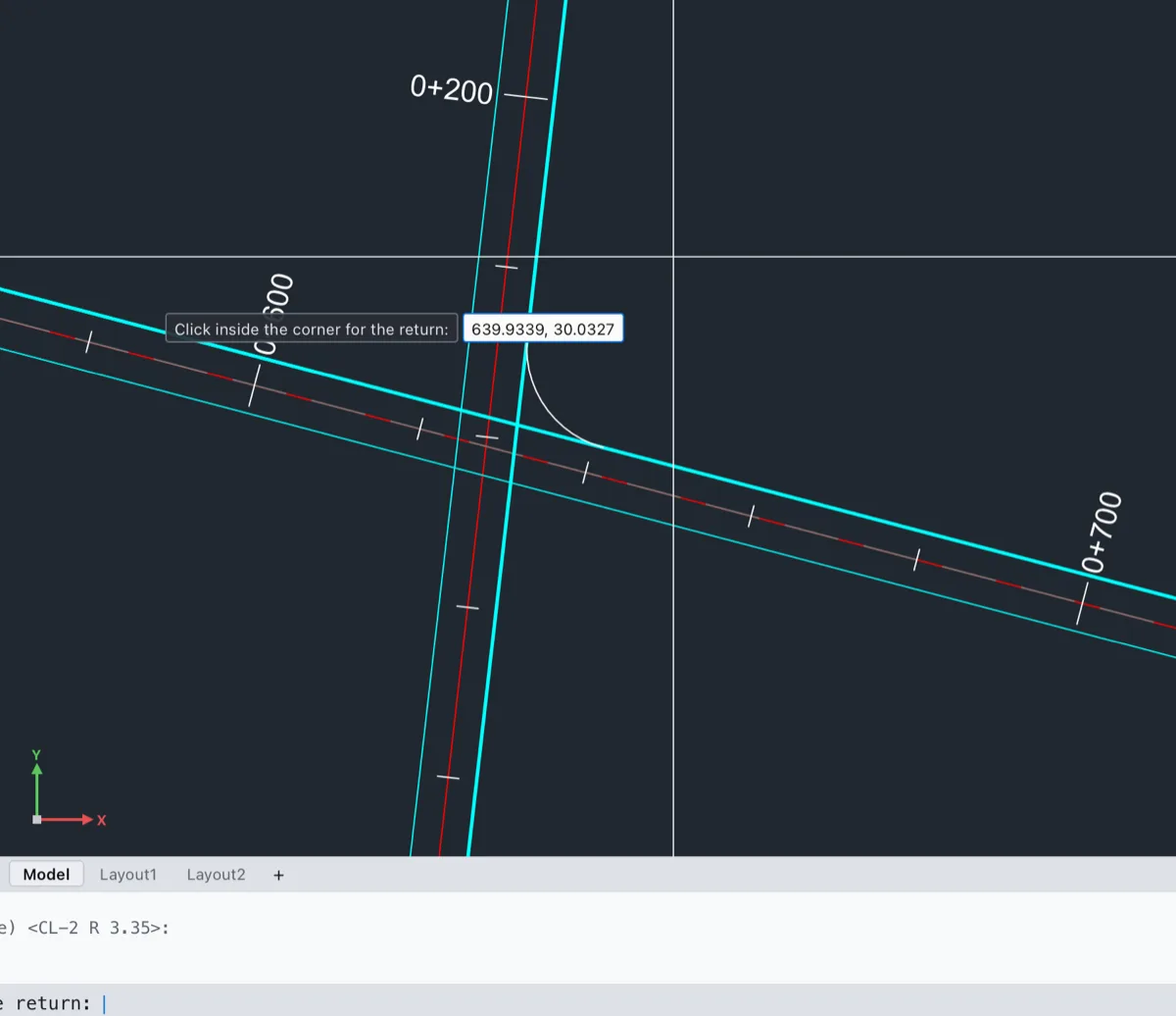
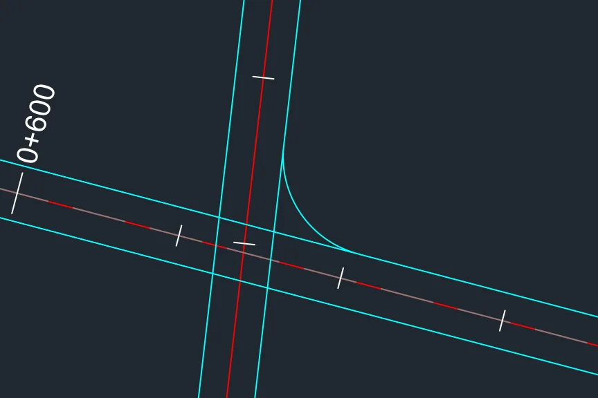
Returns are named CR-1, CR-2… and drawn on C-ROAD-EDGE. To build a whole intersection, make the edges of both roads and add a return in each corner.
Superelevation
Superelevation is the tilt of the road across a curve, so that part of the sideways force is carried by the slope. On a tangent the road has its normal crown (falling both ways from the centerline); approaching a curve it rotates until it slopes fully towards the inside of the curve, then rotates back after.
How Terrace computes it
Superelevation is worked out for every curve of an alignment that has it turned on (new alignments do), with nothing for you to enter:
- The rate comes from the standard's superelevation table for the alignment's e max and design speed, at the curve's radius.
- The runoff (from level crown to full super) is long enough to keep the edge within the standard's maximum relative gradient for the speed, for the lanes rotated and lane width. The runout (from normal crown to level crown) is at the same rate of rotation.
- On curves with spirals, the runoff is the whole spiral: level crown at the TS, full super at the SC.
- On simple curves, two thirds of the runoff is on the tangent and one third on the curve.
- The section turns as a plane about the Pivot: the outside lane goes from −crown to level, to +crown (reverse crown), to the full rate; the inside lane stays at −crown until reverse crown and then follows.
- Between two curves of the same direction (compound curves) the rate changes gradually, not in a step.
- The pavement widening on each curve comes from the standard (DPWH DGCS Table 3-22, at least 0.60 m).
Where to see and change it
Change the inputs in the alignment's Properties, group Superelevation: turn it on or off, choose the Maximum rate, and set the Normal crown, Lanes rotated, Lane width and Pivot. The corridor's lanes tilt by these values, so cross sections and volumes follow at once. The design speed also matters: a faster road needs more superelevation and longer runoff.
To see the stations, open the Superelevation report. Spiral lengths shorter than the runoff, and tangents too short for the transitions between two curves, are reported as problems.
Design checks and the problems list
Every time an alignment changes, Terrace checks it against the standard at its design speed and e max. The checks are:
- a curve radius below the minimum for the speed and e max;
- a spiral shorter than the standard's minimum, or shorter than the superelevation runoff;
- a tangent between two curves too short for their superelevation transitions;
- a curve that doesn't fit between its neighbours (the tangents overlap): it's drawn as an angle point;
- spirals that turn more than the PI deflects (spirals too long for a small turn): the PI gets no curve.
Problems show up in four places:
- the command line, right after the command that made or changed the alignment;
- the Project browser, with a red dot and a ⚠ 2 count beside the alignment;
- the top of the alignment's Properties, as plain sentences with the station and a Zoom to link that zooms the plan to the place;
- the Next step panel, as Fix 2 problems: it selects the first object with problems and zooms to the first one.
Problems never stop you from working: the alignment is still built and everything follows it. Fix them by changing the radius, the spirals or the design speed, or by moving PIs.
Alignment reports
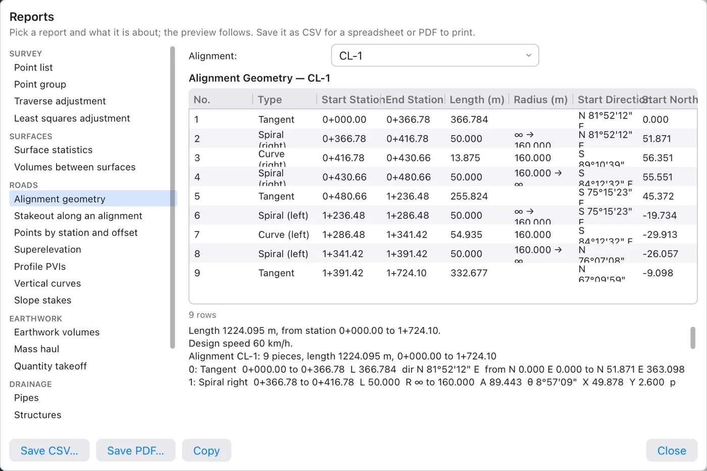
Four reports are about alignments. Open them with Report on the contextual Alignment tab, Report… in Properties, or the object's menu in the Project browser. The Reports dialog opens on Alignment geometry for the selected alignment; pick another report in the list on the left and another alignment at the top.
| Report | Options | What it lists |
|---|---|---|
| Alignment geometry | — | Every tangent, spiral and curve: type and direction of turn, start and end stations, length, radius, start direction (bearing), start and end northing and easting. Under the table, the full listing: deflections, tangent lengths, chords, centers, spiral parameters, the geometry points (TS, SC, CS, ST…) and the superelevation stations. |
| Stakeout along an alignment | Every (20 m by default), Offsets (- left, + right) (a list, like -5, 0, 5), Also at geometry points (PC, PT…) | Station, offset, side, northing, easting and elevation (the design profile's elevation at the centerline, when the alignment has one) of each point to set out. |
| Points by station and offset | Only points (e.g. 1-20, 35) | For survey points: northing, easting, station and offset from the alignment, side and elevation. |
| Superelevation | — | For each curve: end normal crown, level crown, reverse crown, begin and end full super, then reverse crown, level crown and begin normal crown going out, the rate and the widening. |
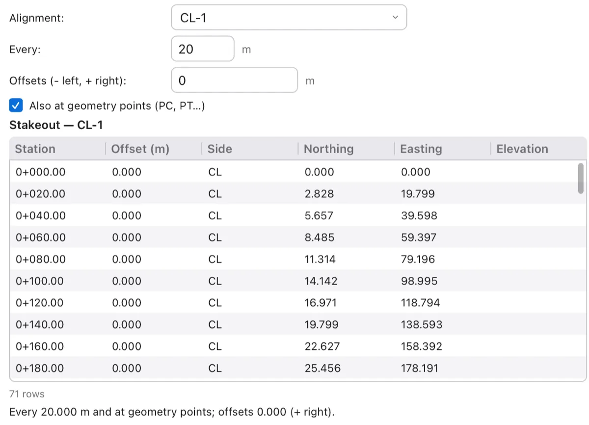
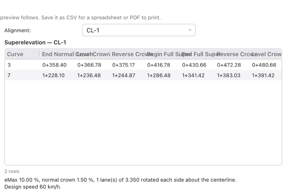
Every report can be saved with Save CSV… (for a spreadsheet) or Save PDF… (to print), or copied with Copy. The Reports chapter covers the dialog in full.
What's next
With the centerline drawn, the next step is its profile: sample the ground along it and design the grade line. See Profiles.