
Standards and styles
This chapter explains the design standards Terrace checks your design against (DPWH and AASHTO), how to read and edit their tables, and the styles and layers that decide how every civil object looks on the plan. You'll be able to choose a standard for a project, make your own office or regional standard, and change how contours, alignments and parcels draw.
What a design standard is
A design standard is a set of tables: for each design speed, the friction factor, sight distances, K values, maximum grades, minimum radii; superelevation rates by radius; typical road classes; rainfall intensities; and limits for storm pipes. Terrace takes its defaults from these tables and checks your design against them. For example:
- A new alignment's curves get a radius allowed at its design speed, and a curve that is too tight shows up as a problem in its Properties.
- Superelevation rates and runoff lengths come from the superelevation table for the alignment's maximum rate.
- A design profile's vertical curve lengths come from K crest and K sag (and never go below the minimum curve length).
- A typical section built from a road class takes its lane and shoulder widths, cross slopes and cut and fill slopes.
- A new pipe network takes its minimum cover, velocities and slope, and its runoff comes from the chosen rainfall station.
Nothing in Terrace hard-codes these numbers: the design tools read them from the tables, so when you edit a table, the design follows.
The built-in standards
| Standard | Units | Where its values come from |
|---|---|---|
| DPWH (default) | metric | DPWH Design Guidelines, Criteria and Standards (DGCS) 2015, Volume 4 Highway Design; DPWH Department Orders (DO 22 s.2011, DO 112 s.2019); HSDS 2012 for road classes; DGCS Volume 3 for drainage pipes; PAGASA rainfall intensity-duration-frequency (RIDF) tables for 16 stations. |
| AASHTO | metric | AASHTO A Policy on Geometric Design of Highways and Streets (the Green Book), 7th edition, 2018; FHWA HEC-22 for pipe velocities. |
| AASHTO US | US customary (mph, ft) | The same Green Book, US tables. |
Every standard lists the exact tables it was built from on its Sources page (see below). Each project keeps its own copy of the standards, saved in the .terrace file, so editing them changes only that project.
Choosing the standard for a project
A project has one current standard. Terrace picks it when the project is made:
- File ▸ New Project (⌘N): DPWH, metric.
- File ▸ New Project With: DPWH (metric), AASHTO (metric) or AASHTO (US feet).
To change it later, use any of these — they all set the same project-wide value:
- Survey ▸ Project Settings, page Units & coordinates, field Design standard.
- The Standard row in an alignment's Properties panel (group Design).
- Use for this project in the Design Standards dialog (next section).
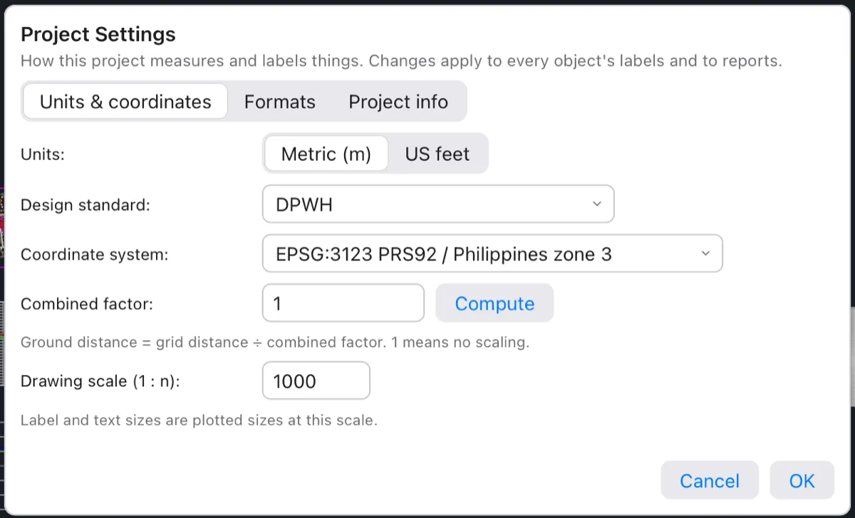
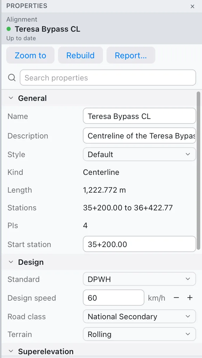
When the standard changes, every alignment and profile is checked again at once, and any new problems appear in their Properties.
The Design Standards dialog
Open it with Survey ▸ Design Standards, or Design Standards… in the command palette (⌘K). It shows the project's standards as buttons along the top — the current one has a tick (DPWH ✓) — and the tables of the one you click, on six pages.
To change a value, double-click a cell, type, and press Enter. Add row copies the last row below it (one speed step up on the speeds page); select rows and click Delete rows to remove them. Nothing is saved until you click OK; Cancel throws every change away.
Design speeds
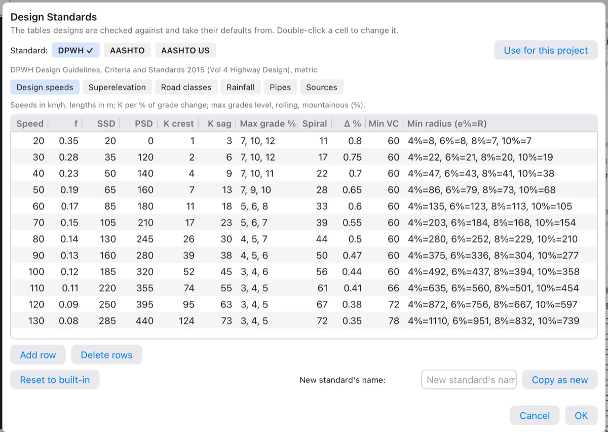
One row per design speed (km/h, or mph in AASHTO US). For a speed between two rows, Terrace interpolates.
| Column | Meaning |
|---|---|
| f | Side friction factor for horizontal curves. |
| SSD, PSD | Stopping and passing sight distance. |
| K crest, K sag | Rate of vertical curvature: the curve length per 1 % of grade change. A vertical curve's length is K × the algebraic grade difference. |
| Max grade % | Maximum grade in level, rolling and mountainous terrain, as three numbers. |
| Spiral | Desirable spiral (transition curve) length. |
| Δ % | Maximum relative gradient between the edge of pavement and the axis of rotation, which sets the superelevation runoff length. |
| Min VC | Minimum vertical curve length (DPWH: 60 m). |
| Min radius (e%=R) | Minimum curve radius for each maximum superelevation rate, written as pairs: 4%=135, 6%=123, 8%=113, 10%=105. Type them the same way. |
Superelevation
Superelevation is the banking of the road on a curve. Choose a Maximum rate (DPWH has e 4 %, 6 %, 8 % and 10 %); the table gives the rate in percent for each radius (rows) and design speed (columns). 0 means normal crown (no banking needed), and -1 means the radius is below the minimum at that speed. Rates between two radii are interpolated.
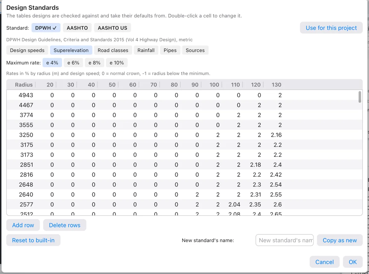
An alignment uses the table matching the Maximum rate in its Properties (group Superelevation).
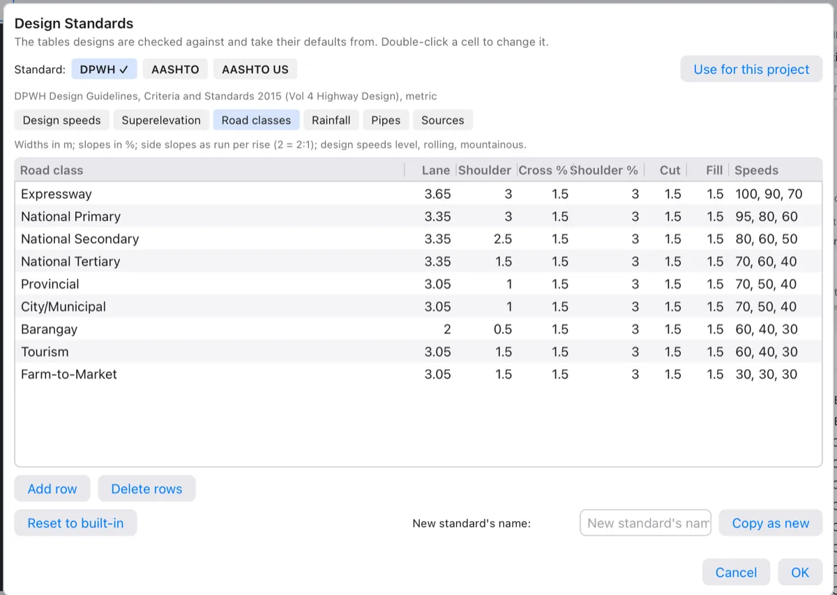
Road classes
Road classes are the typical sections a typical section starts from. Each has lane and shoulder widths, the cross slope of the pavement and of the shoulder (%), cut and fill side slopes (as run per rise: 1.5 means 1.5 horizontal to 1 vertical) and the design speeds for level, rolling and mountainous terrain.
Rainfall
Rainfall intensity-duration-frequency (IDF) tables feed the rational method for storm drainage. Pick a Station; the table gives the intensity in mm/h for each storm duration (rows, in minutes) and return period (columns, in years). The DPWH standard carries 16 PAGASA stations, from Port Area, Manila and Science Garden, Quezon City to Baguio, Davao, Mactan, Iloilo, Tacloban and others. A pipe network chooses its station in its Properties (Rainfall station, group Design storm).
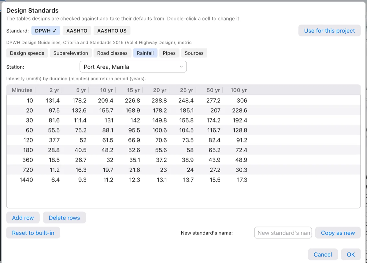
Add row here adds a longer duration (double the last). The AASHTO standards have no rainfall stations; the page says so.
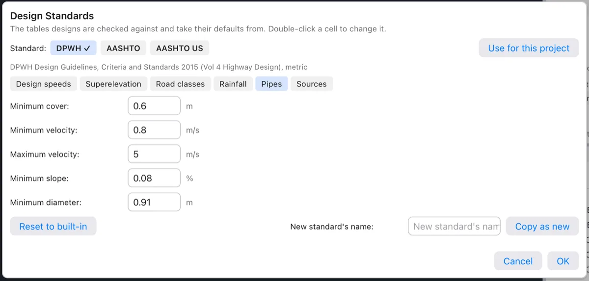
Pipes
Five limits for gravity pipes: Minimum cover, Minimum velocity, Maximum velocity, Minimum slope (%) and Minimum diameter. DPWH gives 0.6 m cover, 0.8 to 5 m/s and a 910 mm minimum pipe; DPWH sets no minimum slope, so Terrace uses 0.08 %, the slope that gives 0.8 m/s in a 910 mm pipe flowing full. A new pipe network takes these as its design rules; an existing network's rules are changed in its Properties.
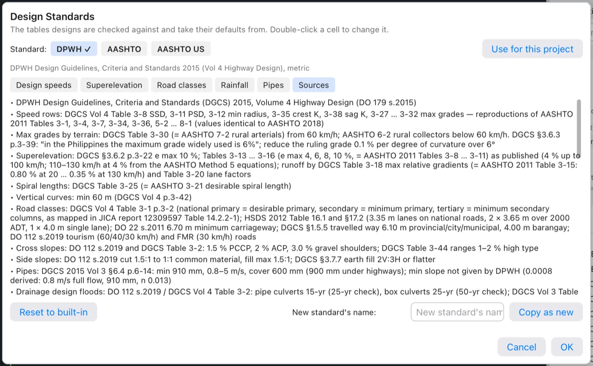
Sources
The last page lists, line by line, which published table each value comes from — DGCS table numbers, Department Orders, the Green Book tables — and where Terrace had to derive a value because the standard doesn't give one. It's read-only; use it when a reviewer asks "where does this number come from?".
Making your own standard
Keep the built-in tables as they are, and make a copy for your office, region or project when you need different values (a regional office's wider shoulders, a local rainfall station).
- Click the standard to start from, such as DPWH.
- Type a name in New standard's name, such as
DPWH Region IV-A, and click Copy as new. The copy appears as a new button and is shown at once; its description reads "Copy of DPWH". - Edit its tables.
- Click Use for this project if the project should use it. The tick moves to it.
- Click OK.
Reset to built-in puts the standard shown back to Terrace's own tables (all pages). It works for DPWH, AASHTO and AASHTO US; your own standards have nothing to go back to, and the dialog says so.
What happens when you click OK
The standards and the current choice are saved in the project as one undo step (Design Standards). Because designs are checked against the tables, Terrace checks again every alignment, every design profile and every pipe network, and redraws what changed. Any new problem — a curve now below the minimum radius, a K value too small — shows in that object's Properties and as a red dot in the Project browser.
Styles: how objects look
A style decides how a civil object draws: which parts show (contours, triangles, station labels, curve labels…), their sizes, and the layer of each part. The object itself — the surface's triangles, the alignment's geometry — doesn't change with its style. Each kind of object has its own styles, and every kind has one called Standard, which is what objects use until you choose another.
Terrace comes with a set of styles for plan production, for example:
- Surfaces: Standard, Contours 1m and 5m, Contours 0.5m and 2.5m, Contours 2ft and 10ft, Triangles and Border, Border Only, Elevation Banding, Slope Banding, Slope Arrows.
- Alignments: Standard, Layout, Geometry Only, Offset (used by offset alignments and curb returns).
- Points: Standard, Marker Only, Number and Elevation.
- Profiles: Existing Ground for ground profiles and Design Profile for design ones; profile views: Major Grids, No Grid.
- Pipe networks: Single Line, and Sanitary for sanitary networks; parcels: Survey Plan; corridors: Feature Lines Only; feature lines: Grade Labels.
Giving an object a style
- Select the object — click it in the plan or in the Project browser.
- In the Properties panel, open the Style row (group General) and pick a style. Default means the kind's usual style.
The object redraws at once, as one undo step. You can also give it a style from the Object Styles dialog, which lets you look at what each style does first (below).
The Object Styles dialog
To change what a style does, or make a new one, open Sheets ▸ Styles (or Styles… in the command palette). With a civil object selected, the button opens the dialog on that object's kind and style; with nothing selected it starts on Surfaces.
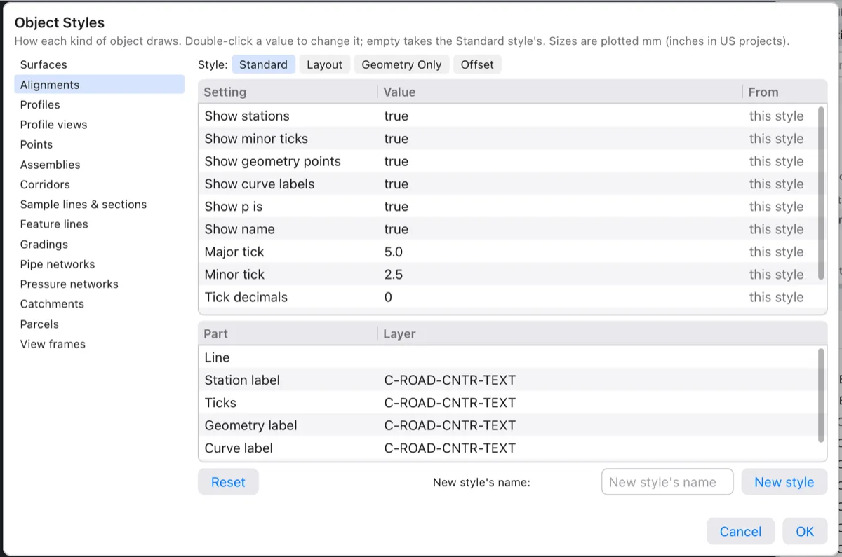
- On the left, click a kind: Surfaces, Alignments, Profiles, Profile views, Points, Assemblies, Corridors, Sample lines & sections, Feature lines, Gradings, Pipe networks, Pressure networks, Catchments, Parcels or View frames.
- Click a style at the top. A style changed in this project has a star (Standard *).
- Double-click a Value to change it. Leave it empty to take the value from the kind's Standard style.
- Double-click a Layer to put that part on another layer. A new layer name is added to the drawing when the object redraws.
- Click OK. Every civil object redraws with the new styles (one undo step, Styles).
The From column says where each value comes from: this style, built-in (Terrace's own version of this style) or Standard. An empty value in a surface style means the surface's own setting in its Properties (such as its contour interval) is used.
Using a style for the selected object
When you open the dialog from Sheets ▸ Styles with an object selected, it shows a check box under the tables: Use style for object. It's a quick way to try a style and give it to the object in one go.
- Select the object, for example the Teresa Bypass CL alignment (click it in the plan or in the Project browser).
- Click Sheets ▸ Styles. The dialog opens on Alignments, on the style the alignment uses (Standard for Default).
- Click another style at the top, such as Layout, and read its settings. Change any of them if you like.
- Tick Use Layout for Teresa Bypass CL and click OK.
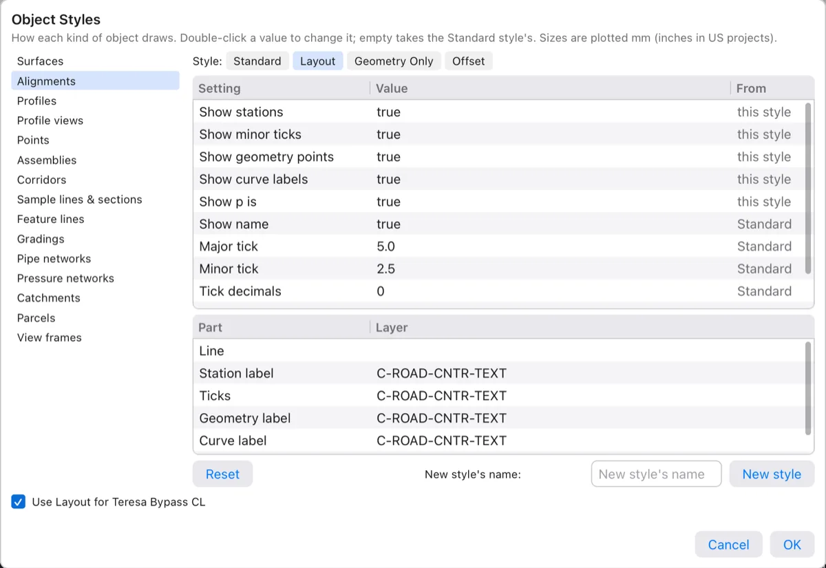
The alignment's Style row in Properties now reads Layout, and it redraws with it. Style edits and the new style go in as one undo step (Styles). The check box shows only while the dialog is on the selected object's kind; picking Standard there sets the object back to Default.
New styles and Reset
To make a new style, pick the one to start from, type a name in New style's name (for example Plan Sheets) and click New style; it copies every value and layer. Reset drops this project's changes to a built-in style, or deletes a style of your own (objects using it then draw as Standard).
The common settings
Settings are true/false switches, numbers or names. Sizes (text heights, marker sizes, tick lengths, gaps) are in plotted millimetres (inches in US projects): Terrace multiplies them by the drawing scale in Project Settings (1:1000 in the sample), so labels come out the right size on paper.
| Kind | Main settings |
|---|---|
| Every kind | Text height, text style (a drawing text style, "Standard"). |
| Points | Marker (cross-circle, cross, x, circle, dot, point, none), marker size, show number / elevation / description. |
| Surfaces | Minor and major contour interval; show contours, triangles, border, points, slope arrows; analysis (elevation or slope banding); contour label decimals and gap; number of bands; slope bands; spot decimals. |
| Alignments | Show stations, minor ticks, geometry points (PC, PT…), curve labels, PIs, name; major and minor tick size; decimals on station labels. |
| Profiles | Show PVIs, curve labels, grade labels, tangents. |
| Profile views | Show grid, heavier grid every n lines, title and its height, elevation decimals, band text height, pipe labels. |
| Sample lines & sections | Show sample lines and their labels, volume table; cut and fill hatch patterns and scale; title height; gap between section views; mass haul height. |
| Pipe networks | Pipes drawn as double (outside walls) or single lines; labels; flow arrows; minimum symbol size. |
| Catchments | Hatch, its pattern and scale; label; flow path. |
| Parcels | Parcel labels, segment bearing/distance labels, corner numbers, area table and where it goes, parcel text height. |
| Others | Corridors (feature lines, section lines, colors by point code), feature lines, gradings (daylight, projection lines, slope ticks, volume label), pressure networks, view frames (frames, match lines, labels). |
Layers
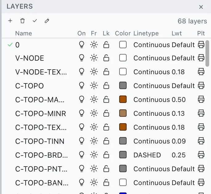
Each part of a civil object sits on its own layer, so you can turn contours off, plot the existing ground grey, or freeze labels while you work, with the ordinary layer tools. Terrace names its layers after the US National CAD Standard (NCS/AIA): a discipline letter (C civil, V survey), a major group (TOPO, ROAD, STRM…) and modifiers. The layers come with colors, linetypes and lineweights, and are added to the drawing the first time an object uses them.
| Objects | Layers |
|---|---|
| Survey points | V-NODE (markers), V-NODE-TEXT (labels). A description key's layer wins over both. |
| Surfaces | C-TOPO-MAJR and C-TOPO-MINR (contours), C-TOPO-TEXT, C-TOPO-TINN (triangles), C-TOPO-BRDR (border, dashed), C-TOPO-PNTS, C-TOPO-BAND (analysis), C-TOPO-SLOP (slope arrows), C-TOPO-SPOT. |
| Alignments | C-ROAD-CNTR (geometry), C-ROAD-CNTR-TEXT, C-ROAD-CNTR-TANG (PI tangents); C-ROAD-OFST for offset alignments and curb returns. |
| Profiles and profile views | C-ROAD-PROF (design), C-ROAD-PROF-EXST (ground, dashed), C-ROAD-PROF-TEXT, C-ROAD-PROF-TANG, C-ROAD-PROF-VIEW, C-ROAD-PROF-GRID, C-ROAD-PROF-BAND. |
| Assemblies and corridors | C-ROAD-ASSM, C-ROAD-CORR, C-ROAD-CORR-SCTN. |
| Sections and mass haul | C-ROAD-SCTN (sample lines), -TEXT, -VIEW, -GRID, -EXST, -DSGN, -PATT, -TABL; C-ROAD-MASS, -GRID, -TEXT. |
| Grading | C-GRAD (daylight), C-GRAD-FEAT, C-GRAD-PROJ, C-GRAD-TEXT. |
| Drainage and water | C-STRM, C-STRM-STRC, C-STRM-TEXT, C-STRM-PROF, C-STRM-CTCH and -PATT (catchments); C-SSWR… for sanitary sewers; C-WATR, C-WATR-FITT, C-WATR-TEXT for water mains. |
| Parcels | C-PROP (lot lines), C-PROP-RWAY (right of way, phantom), C-PROP-ESMT, C-PROP-TEXT, C-PROP-TABL. |
| Sheets | C-ANNO-VFRM (view frames), C-ANNO-MTCH (match lines), C-ANNO-TEXT. |
Tip To change a layer's color or lineweight, change the layer in the Layers panel — every object on it follows. To move a part to another layer, change the style's Layer for that part.