
Grading
This chapter shows how to shape ground that isn't a road: building pads, yards, ponds and embankments, made from feature lines and graded out to the existing ground. You'll be able to draw a feature line, set its elevations and grades, grade it to a surface, read the cut and fill, and raise or lower it until cut and fill balance.
How grading works in Terrace
Grading has two kinds of objects:
- A feature line is a line with an elevation at every point — the edge of a pad, the top of a bank, the bottom of a ditch. It can have straight segments and arcs, and extra elevation points (grade breaks) between its corners.
- A grading projects a slope out from a feature line until it reaches a target: the existing ground, an elevation, a height above or below the line, or a distance. Where the slope meets the ground is the daylight line.
Gradings belong to a grading group (shown in the Project browser as Grading 1, Grading 2…). A group builds its own surface (Grading 1 Surface, listed under Surfaces) from the feature lines, the slopes and the inside of closed pads, and compares it with the existing ground to give cut and fill volumes. Everything stays linked: change a feature line's elevation and the slopes, the surface and the volumes follow by themselves.
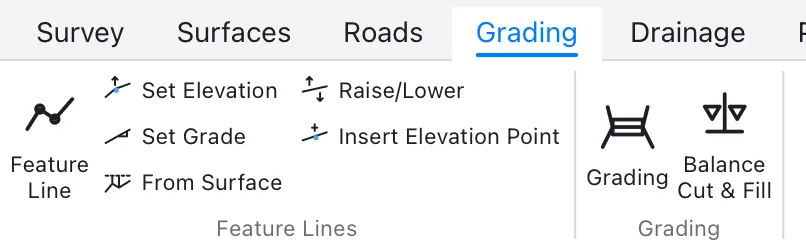
All the tools are on the Grading ribbon tab, in two groups: Feature Lines and Grading. Every command is also on the command line (see the grading commands) and each one is a single undo step.
The pictures in this chapter use the sample project (Help ▸ Open the Sample Project): a 40 m × 25 m building pad drawn on the slope north of the Teresa Bypass Road, near Km 35+720, and graded to the EG (existing ground) surface. Point labels and view frames are turned off to keep the plan clear.
Drawing a feature line
Draw a feature line for any edge whose elevations you want to control. You can click its points one by one with an elevation for each, or turn existing polylines, lines and arcs into feature lines.
By clicking points
- Click Grading ▸ Feature Line, or type
FEATURELINE(FEAT). - At Specify start point or [Object], click the first point (or type its coordinates, such as 522910,1610365).
- Terrace asks Specify elevation or [Surface]. The default in angle brackets is the ground elevation under the point, read from the existing-ground surface. Press Enter to take it, type an elevation, or type S to take the surface elevation.

The default elevation is the ground under the point (54.866 m here). - Click the next point and give its elevation. After the first point, the default is the elevation you gave last, so a level pad is just Enter after each click. A rubber band shows the line as you move.
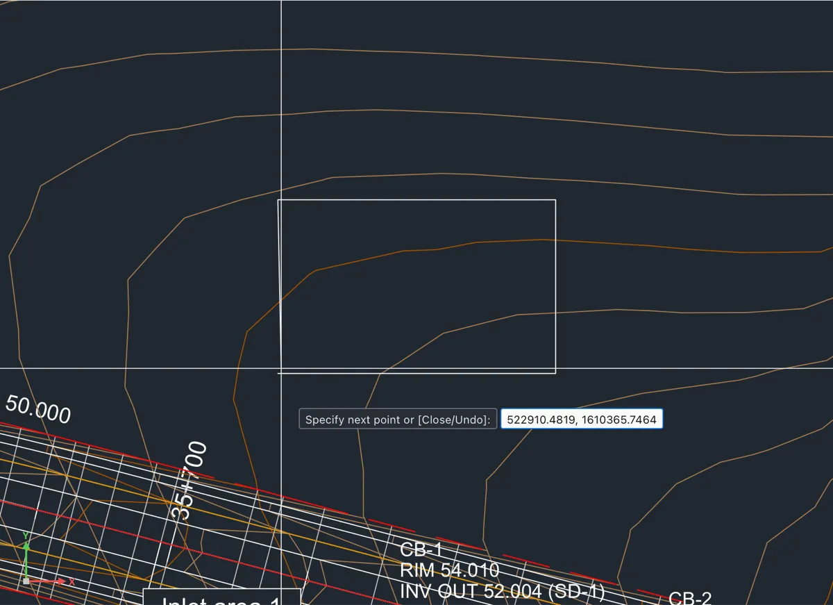
Three corners placed at elevation 57.00; the line follows the cursor. - Keep going. U (Undo) takes back the last point. From the third point on you can type C (Close) to close the line back to its start — a pad. Enter ends an open line.
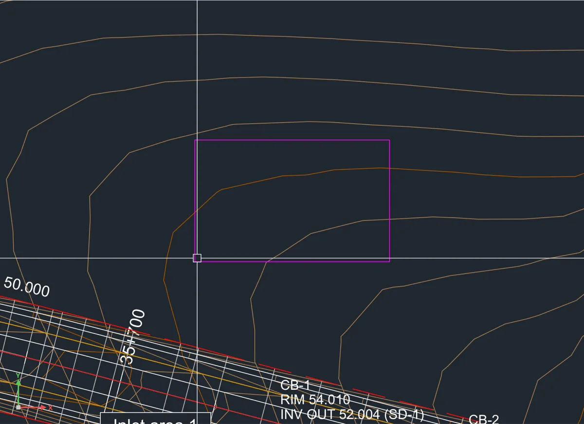
The line is named FL-1, FL-2… and the command line says how many vertices it has and how long it is, for example Feature line FL-1: 4 vertices, 130.000 long. It is drawn on layer C-GRAD-FEAT.
From polylines, lines and arcs
If the edge is already drawn — a pad outline from the architect, a ditch line — convert it instead of tracing it.
- Start
FEATURELINEand type O (Object), or just press Enter at the first prompt. - Select the polylines, lines or arcs and press Enter.
- At Elevation for the feature lines or [Surface], type one elevation for all of them, or type S to drape them on the existing ground (they then get an elevation point wherever they cross a triangle of the surface).
Arcs stay arcs. A 3D polyline, or a polyline that already has an elevation, keeps its own elevation unless you chose S. Each object becomes its own feature line, and the command line lists the names made.
Editing elevations and grades
Once a line exists, the five buttons in the Feature Lines group change its elevations. Each starts by asking for the feature line (Select feature line): click it, type its name, or press Enter for the one shown in angle brackets (the selected one, or the last one you used).
Set the elevation of a vertex
Set Elevation (SETELEVATION, SETELEV) changes the elevation of individual corners.
- Start the command and pick the feature line.
- At Select a vertex, click near a corner. Terrace takes the nearest vertex.
- At Elevation of vertex 1, type the new elevation (the default is its current one).

Setting a corner of the pad. - The command asks for the next vertex, so you can set several corners in one go. Press Enter to finish. All the changes are one undo step.
Set the grade between two vertices
Set Grade (SETGRADE, SETGR) gives a stretch of the line a constant grade — for example a 1 % fall across a pad for drainage.
- Start the command and pick the feature line.
- Click the start vertex, then the end vertex.
- At Grade in percent (+ rises toward the end vertex), type the grade. The default is the grade the line has between those vertices now.
The start vertex keeps its elevation. Every vertex and elevation point after it, up to the end vertex, is set to the start elevation plus grade × distance. On a closed line the grade runs the shorter way round between the two vertices.
Take elevations from a surface
From Surface (ELEVATIONSFROMSURFACE, ELEVFROMSURF, EFS) drapes a feature line on a surface — useful for the toe of an existing bank or a ditch that follows the ground.
- Start the command and pick the feature line.
- Pick the surface (the default is the existing ground).
- At Add grade breaks where it crosses the surface's triangles? [Yes/No], press Enter for Yes. With Yes the line follows the ground exactly between corners; with No only the corners take the ground elevation.
This copies the elevations once. To keep a line glued to a surface — so it follows when the surface changes — set Elevations from in its Properties instead (see below).
Raise or lower a whole line
Raise/Lower (RAISELOWER, RAISE, LOWER) moves every elevation of a line up or down by the same amount. Pick a feature line, or pick a grading group to move all the feature lines it is graded from. At Raise by (negative lowers) type the change, for example 0.25 or -0.5 (the default is the last value you used, at first 0.5).
Add a grade break
Insert Elevation Point (INSERTELEVPOINT, IEP, ELEVPOINT) adds an elevation point between two corners: a place where the grade changes without a bend in plan, such as a high point along a pad edge.
- Start the command and pick the feature line.
- At Specify a point on the feature line, click on the line. Terrace uses the closest point of the line.
- At Elevation, type the elevation (the default is the elevation the line has there now). Clicking right on a corner sets that corner's elevation instead.
- The command asks for the next point; press Esc when you are done.
Moving vertices with grips
Select a feature line and its vertices show grips. Drag one to move that corner in plan: it keeps its elevation, and the gradings, the group surface and the volumes update as you let go (one undo step). See Selecting and editing for grips, MOVE and ERASE on civil objects.
Feature line properties
Select a feature line to see it in the Properties panel:
| Row | What it does |
|---|---|
| Name | The line's name (FL-1…). |
| Style | How it is drawn (see Standards and styles). |
| Length, Vertices | Plan length and number of corners (marked "closed" for a closed line). Read only. |
| Elevations from | A surface the line follows. While set, the line takes that surface's elevations at every corner and elevation point, and takes them again whenever the surface changes. Choose None to keep its own elevations. |
| Above the surface | Shown when Elevations from is set: how far above the surface the line sits (negative = below). |
Grading from a feature line
Grade a feature line to make the slopes between it and the ground: the side slopes of a pad, the banks of a pond, an embankment for a yard. There are two ways: Grading ▸ Grading on the ribbon opens the New Grading dialog, with every choice on one form; the GRADING command asks one prompt at a time and takes its slopes from the design standard. This section follows the command; the dialog is below.
- Type
GRADING(GRADE,GRD). - At Select feature line to grade from or [Dialog], pick the line (or press Enter for the one shown). Typing D closes the command and opens the New Grading dialog instead.
- Grade which side: for a closed line choose Inside, Outside or Both (default Outside — the slopes around a pad); for an open line choose Left, Right or Both (default Both), looking along the line from its first point.

A closed line grades outside by default. - Grade to: Surface, Elevation, Relative or Distance. The default is Surface when the project has a ground surface. The next prompts depend on this choice (table below).
- Answer the slope prompts. Slopes are written run : rise: 2 means 2 m out for every 1 m up or down (2:1, 50 %). The defaults come from the current standard's road class: for DPWH, cut 1.5:1 and fill 1.5:1.
| Grade to | Prompts | What you get |
|---|---|---|
| Surface | Select target surface (default: the existing ground), Cut slope (run:rise), Fill slope (run:rise) | Where the ground is above the line the slope goes up at the cut slope; where it is below, down at the fill slope; each stops where it meets the ground (the daylight). |
| Elevation | Target elevation (default 2 m below the line's first point), Slope (run:rise) | The slope runs out until it reaches that elevation — for example the floor of a pond. |
| Relative | Height above the feature line (negative = below) (default −1.0), Slope (run:rise) | The slope runs until it is that much above or below the line, wherever it is. |
| Distance | Distance out (default 5.0), Grade in percent (negative falls away) (default −2 %) | A strip of fixed width at a grade, such as a 5 m apron falling at 2 %. |
Watch out In this version the command's Distance choice applies the grade 100 times too flat: −2 % comes out as −0.02 %, so the strip is almost level. Use the New Grading dialog (Grade to Distance) for a strip at a grade.
Terrace builds the grading at once and reports it on the command line:
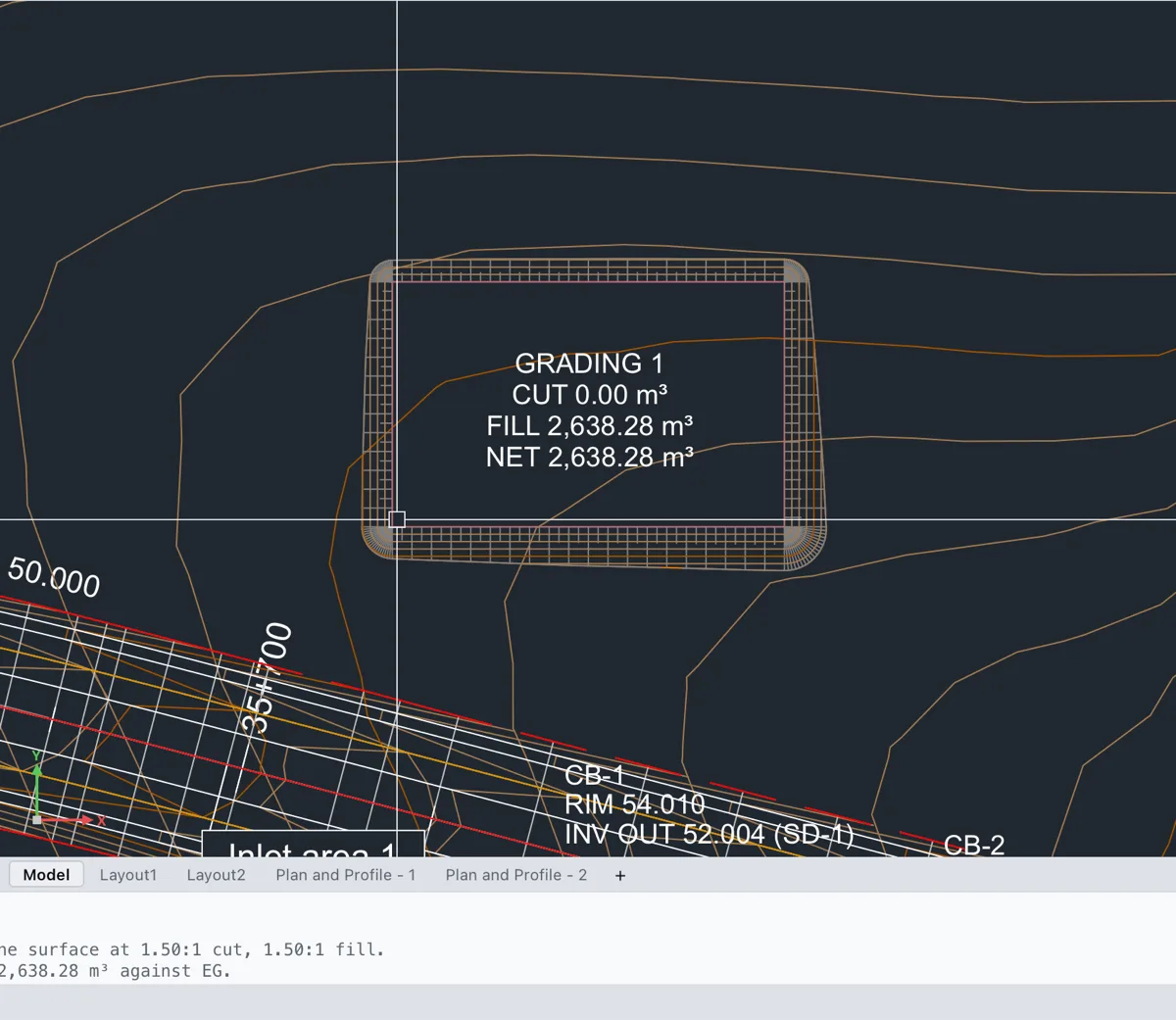
In the plan you see the daylight line (layer C-GRAD), projection lines from the feature line to the daylight with short ticks on the slope, and a label with the group's cut, fill and net volume. Around convex corners the slopes are rounded (a fan of projections, as in the picture); at inside (concave) corners they meet in a mitre.
If the feature line is already in a grading group, the new grading joins that group and replaces any earlier grading on the same side; otherwise a new group is made (Grading 1, Grading 2…). A closed line's group fills its inside, so the pad top is part of the surface.
Note If a projection can't reach its target — the ground runs out, or the slope never meets it — the grading still builds and the problem is listed in the group's notes (on the command line and in Properties). Check that the target surface covers the area around the line.
The New Grading dialog
The dialog makes a grading with all the choices on one form. Open it with Grading ▸ Grading on the ribbon, or by typing D at the first prompt of GRADING. It opens on the selected feature line (else the first one).
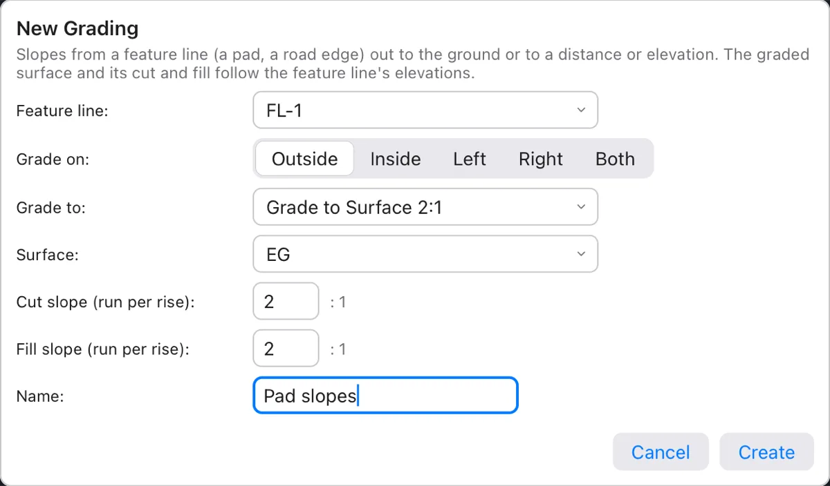
| Field | What it does (default) |
|---|---|
| Feature line | The line to grade from (the selected one, else the first). |
| Grade on | Outside (default), Inside, Left, Right or Both. On an open line, Inside means left and Outside means right. |
| Grade to | A preset: Grade to Surface 2:1 (default), Grade to Distance, Grade to Elevation or Grade to Relative Elevation. The fields below change with it. |
| Surface | For Grade to Surface: the surface to daylight on (EG, else the first surface). |
| Distance, Grade | For Grade to Distance: how far out, and the grade in percent (5 m at −2 %). |
| Elevation / Height (+ up, - down) | For Grade to Elevation, the target elevation; for Relative Elevation, the height above or below the line. |
| Cut slope (run per rise), Fill slope (run per rise) | 2 : 1 each. (The dialog doesn't take the standard's slopes as the command does; type 1.5 for the DPWH 1.5:1.) |
| Name | The grading group's name. The first is Grading 1; when that exists this version proposes Grading 1 2, so type a name of your own. |
Click Create. Terrace makes a new grading group every time (unlike the command, which adds to the line's existing group), compares it with the surface you chose, and reports the volumes in m³. The pad graded at 2:1 says Pad slopes made: cut 124.2, fill 126.2.
If no feature line exists yet, Create says so at the bottom of the dialog: draw one first (above).
The grading surface and its volumes
Each grading group makes a surface named after it (Grading 1 Surface). It is built from the feature lines, the daylight lines and the projection lines as breaklines, with the footprint of the gradings as its boundary, and the inside of closed lines filled when Fill the inside is on. You can use it like any surface — contours, a profile, a volume against another surface (see Surfaces).
The group compares its surface with its existing ground: cut is where the existing ground is above the grading, fill where it is below; net = fill − cut. These are bank volumes (no shrink or swell factor).
Select the group (click its slopes, or pick Grading 1 in the Project browser or with ⌘K) to see it in Properties:
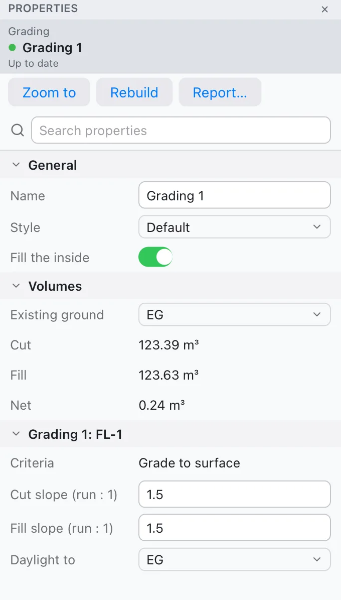
| Row | What it does |
|---|---|
| Name, Style | The group's name and drawing style. |
| Fill the inside | Whether closed feature lines are filled across (a pad) or left open (a ring of slopes only). |
| Existing ground | The surface the volumes are measured against. |
| Cut, Fill, Net | The volumes. Read only; they update with every change. |
| Grading n: line | One section per grading: its criteria (read only), Cut slope (run : 1), Fill slope (run : 1), and for surface targets Daylight to, the target surface. |
Change a slope here and the daylight, the surface and the volumes rebuild at once. Zoom to and Rebuild at the top of the panel work as for every object.
Balancing cut and fill
A pad that needs neither borrow nor waste is cheaper to build. Balance Cut & Fill (GRADINGBALANCE, BALANCE, GBAL) finds the pad elevation where the cut is enough to make the fill.
- Click Grading ▸ Balance Cut & Fill.
- At Select grading to balance, pick the grading group. It needs an existing ground to compare with.
- At Fill factor (cut = fill × factor; 1.25 allows for shrinkage), press Enter for 1.00 (equal bank volumes) or type a factor. With 1.25, Terrace looks for 1.25 m³ of cut for every m³ of fill, because cut soil compacted into fill takes less room.
Terrace raises or lowers all the group's feature lines together until cut ≈ fill × factor (to within 0.1 % of the volume moved, at least 0.5 m³) and says how far it moved them:
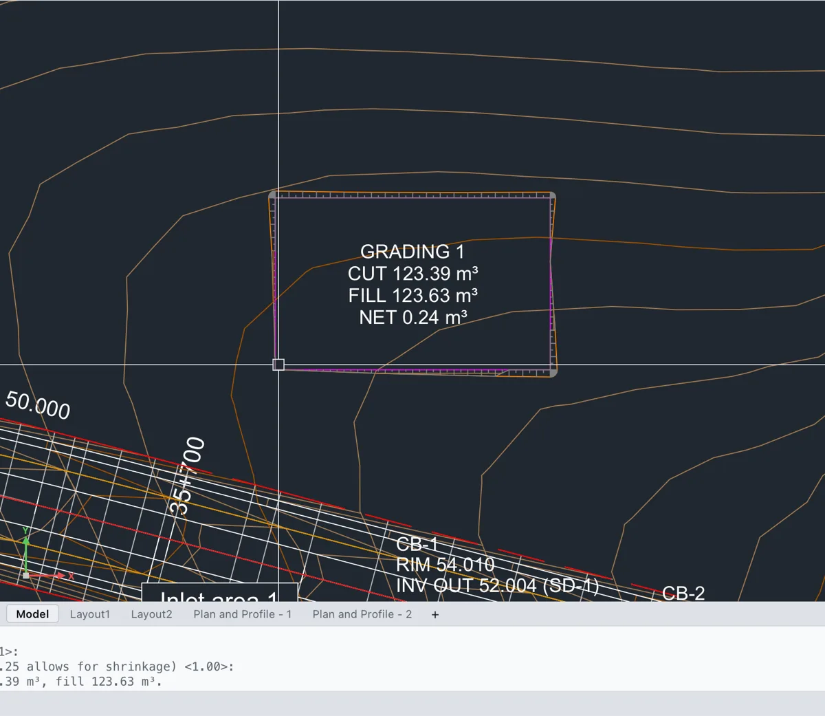
The pad keeps its shape and its grades; only its height changes. Run SETELEVATION afterwards if you want a round number, and the volumes update again.
Good to know
- The command's grading slopes come from the standard's road class (DPWH: 1.5:1 cut and fill); the dialog starts at 2:1. The command remembers the last slopes, distances and grades you typed and offers them next time.
- Every grading command is one undo step; the undo history (Selecting and editing) lists them by name.
- To check the result, look at the grading surface's contours, or compare it with EG using
SURFACEVOLUME(see Surfaces). - Gradings use rounded corners. Corner style (chamfered, mitred) and benches are not yet settable in the app: no command, dialog or Properties row sets them.