This chapter covers storm drains and sanitary sewers, the catchments that feed them, their design by the rational method with PAGASA rainfall, and water mains. You'll be able to lay out a network by clicking, size its pipes and set its inverts, check the hydraulic grade line, read the problems Terrace finds, and print pipe and structure tables.
What Terrace models
A pipe network is a gravity system of structures (manholes, catch basins, inlets, junction boxes, headwalls, outfalls) joined by pipes. It is either a storm drain or a sanitary sewer. Water flows from structure to structure down to one outlet, so a network is a tree: no loops, one pipe out of each structure.
A catchment is an area that drains to one structure. It has a runoff coefficient C and a time of concentration Tc (how long rain takes to flow from its far end to the outlet).
A pressure network is a water main: pipes laid at a set cover below the ground, with fittings at bends and ends.
Rims follow the network's ground surface, design flows come from the catchments, and pipe sizes and inverts follow the network's rules (cover, slope, velocity, drops). Change the ground or a catchment and the network's flows, grade lines and problems update by themselves.
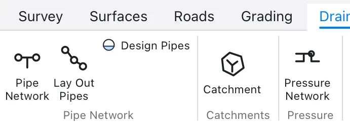
The tools are on the Drainage ribbon tab: Pipe Network, Lay Out Pipes and Design Pipes in the Pipe Network group, Catchment, and Pressure Network. On the command line they are in the drainage commands.
The Drainage tab.
The sample project's drainage
The sample project (Help ▸ Open the Sample Project) has two finished networks on the Teresa Bypass Road, where the road crosses a creek in a sag near Km 35+840:
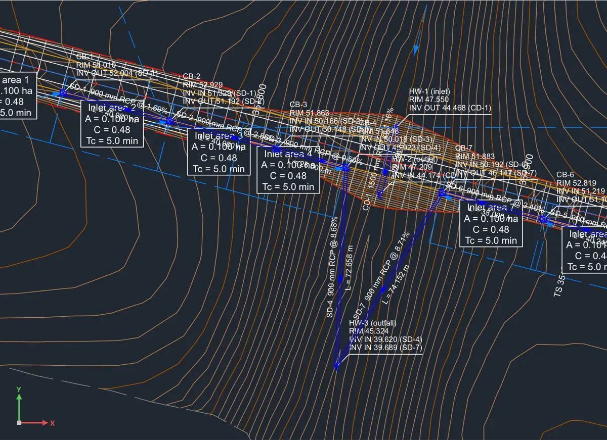
Cross Drain CD-1, a reinforced concrete pipe culvert under the road between two headwalls, carrying the 25-year flood of the creek's 24 ha catchment.
Storm Drain SD-1, seven catch basins (CB-1 to CB-7) at the right shoulder on both approaches of the sag, piped to a headwall (HW-3) that discharges on the creek. Each basin takes an Inlet area catchment: 40 m of the road's right half plus the roadside 25 m out, 0.100 ha with a weighted C of 0.48 (PCCP and shoulder at 0.90, grassed slope at 0.35). The design storm is 10 years at PAGASA's Science Garden, Quezon City station.
Storm Drain SD-1 and Cross Drain CD-1 in the sample project.
Creating a network and laying out pipes
A network is made in two parts: first the network itself (its kind, ground surface, alignment and design storm), then its structures and pipes, laid out by clicking. The ribbon button opens a dialog for the first part; the typed command does both in one go at the command line.
The New Pipe Network dialog
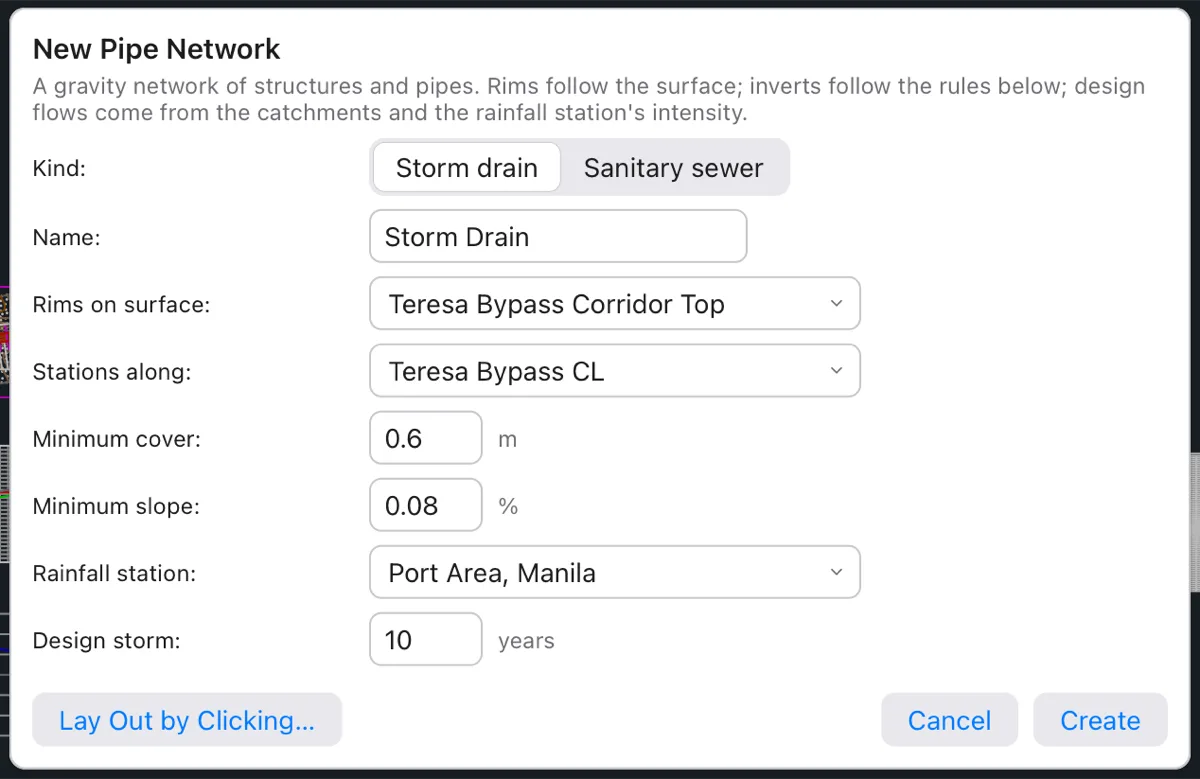
Click Drainage ▸ Pipe Network. The New Pipe Network dialog opens with everything filled in.
The New Pipe Network dialog with its defaults on the sample project.
Check the fields:
Kind: Storm drain (the default) or Sanitary sewer.
Name: Storm Drain to start with (a number is added if the name is taken).
Rims on surface: the surface the rims and the cover follow. Terrace picks a corridor's Top surface when there is one (the finished road), else EG.
Stations along: the alignment the reports measure stations and offsets from — the selected alignment, or the project's road.
Minimum cover and Minimum slope: from the standard (DPWH 0.6 m and 0.08 %).
Rainfall station and Design storm (return period, 10 years): for storm drains only. The standard's first station is chosen (for DPWH, Port Area, Manila); pick the one nearest your project.
Click Create. Terrace makes the empty network and says Pipe network Storm Drain made: lay out pipes with Layout Pipes (click structures along the run). Then use Lay Out Pipes (see below) to add its structures and pipes.
To lay out at once instead, click Lay Out by Clicking…: the dialog closes and CREATENETWORK starts at the command line, as below. What you set in the dialog isn't used then; the command asks for name and kind itself.
By the command line
Type CREATENETWORK (NETWORK, STORMNET).
At Network name [Dialog], press Enter for Storm 1 or type a name. Type D (Dialog) to open the New Pipe Network dialog instead.
The first prompt offers the dialog.
At Kind of network [STorm/SAnitary], press Enter for a storm drain, or type SA for a sanitary sewer.
Storm or sanitary.
Terrace makes the network with the standard's rules and says so: Pipe network Storm 1 (storm): rules from DPWH, min cover 0.60, min slope 0.08%.
The layout starts at once. At Specify structure location, click where the first structure goes. Click on an existing structure of the network to start the run from it instead.
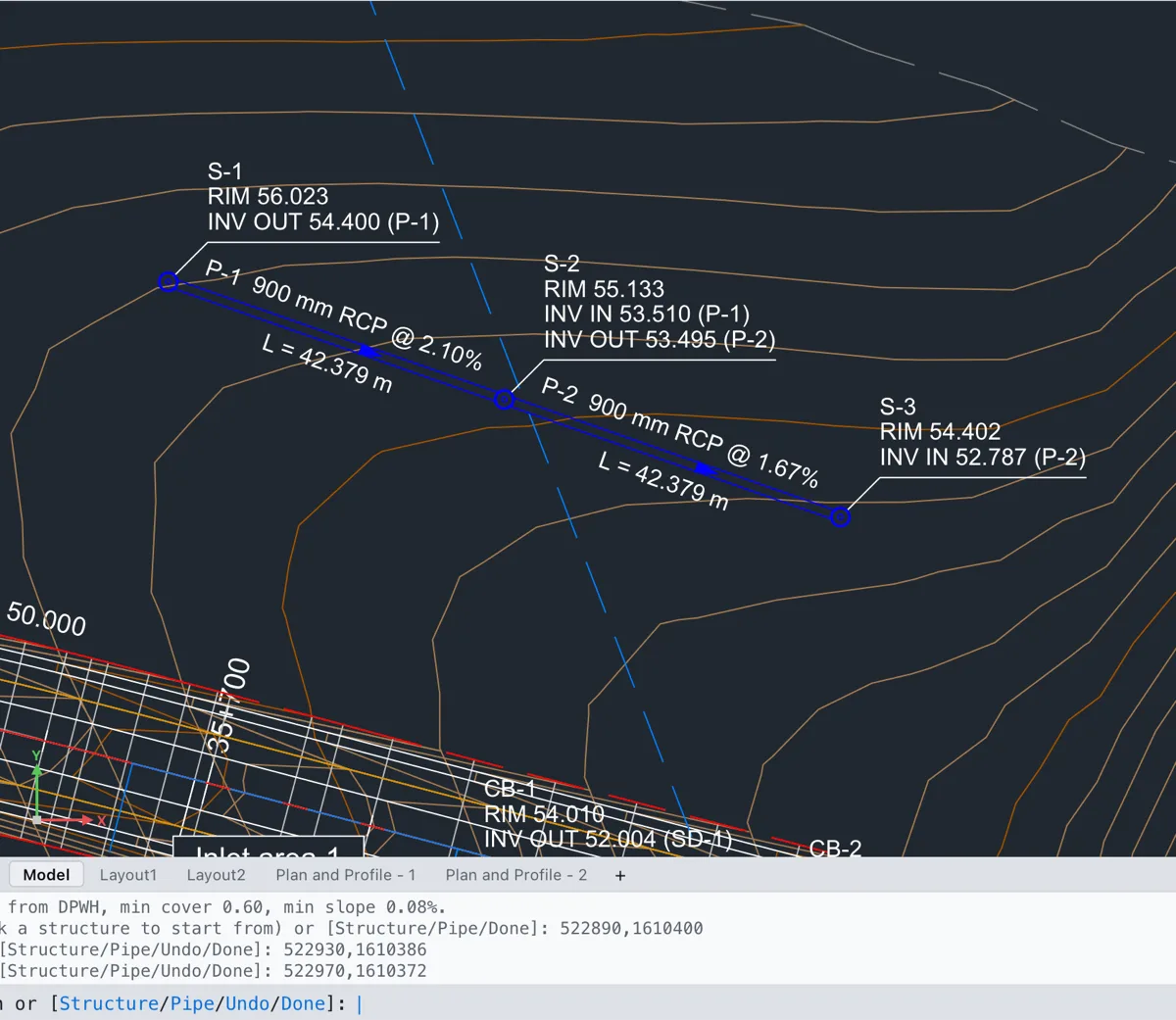
Click the next structure location. Each click adds a structure and the pipe from the previous one; a rubber band shows the next pipe. Clicking an existing structure connects the pipe to it (that's how two runs join at a manhole). Click in the direction the water flows: each pipe flows from the structure before to the new one, so the last structure of the main run is the outlet.
Three structures and two pipes laid out by clicking.
Use the options as you go:
S (Structure) or P (Pipe) lists the network's parts with numbers; type a number or a name (part of a name will do, such as Catch Basin 0.9) to use that part for the next structures or pipes.
U (Undo) takes back the last structure and pipe.
D (Done) or Enter finishes.
When you finish, the command line counts the parts and lists the first problems (see What the problems mean):
The layout is one undo step.
To lay out a network made with the dialog, or to add to a network later, use Lay Out Pipes (LAYOUTPIPES, LAYPIPES, PIPES): pick the network, then click exactly as above.
What Terrace fills in
Names: structures S-1, S-2…; pipes P-1, P-2…
Parts: structures are 1.2 m manholes unless you choose another part; pipes are the smallest circular RCP at least the standard's minimum diameter — DPWH asks for 910 mm, so RCP 900 mm (ASTM C76M's nominal size).
Rims come from the network's ground surface — the existing ground (EG) when the network is made with the command, the surface you chose when it is made with the dialog.
Inverts are set by the rules from upstream down: minimum cover over the pipe, minimum slope, and the pipes matched at each structure (crowns matched, by default).
Design storm: the standard's first rainfall station (for DPWH, Port Area, Manila) unless you chose another in the dialog, a 10-year return period and a 5-minute minimum inlet time. Change them in Properties before designing.
Storm networks draw on layer C-STRM, sanitary on C-SSWR. A sanitary sewer is designed to flow at most 75 % full (storm: 80 %).
The parts catalog
Every network carries its own copy of the catalog. In metric projects it has:
Manholes 1.2, 1.5, 1.8, 2.1, 2.4 m; Catch Basin 0.9 × 0.9 m and 1.2 × 1.2 m; Grate Inlet 0.5 × 1.0 m; Curb Inlet 1.5 m and 3.0 m; Junction Box 1.2 × 1.2 m; Headwall; Outfall; Null Structure
US projects get the inch sizes of the same families. Manning's n values follow HEC-22 Table 7-1.
Moving structures
Select a network and every structure shows a grip. Drag one to move the structure; its pipes follow and its rim is read again from the surface. Pipe sizes and inverts are not changed by a move — run Design Pipes again afterwards.
Catchments
A catchment tells the design how much water reaches each structure. Make one for every inlet, or one for each area that drains to a manhole.
Click Drainage ▸ Catchment, or type CATCHMENT (CATCH, WATERSHED).
Give the boundary in one of three ways:
By clicking: click the boundary's corners; U takes one back; C (Close) or Enter closes it (at least 3 points).
From a polyline: type O (Object) and select a closed polyline.
By delineation: type D (Delineate) — the default when the project has a surface — and click the outlet, the point where the water leaves. Terrace traces on the surface the whole area that drains to that point. Pick a low point or a point in a channel; on a slope with nothing draining to it, it says so and asks again.
At Runoff coefficient C (0.30 grass … 0.95 pavement), type C for the area (default 0.50).
C for the area.
At Select the structure it drains to or [None], press Enter for the structure shown (the one nearest the outlet, or the boundary's centre), click another structure, or type N for none.
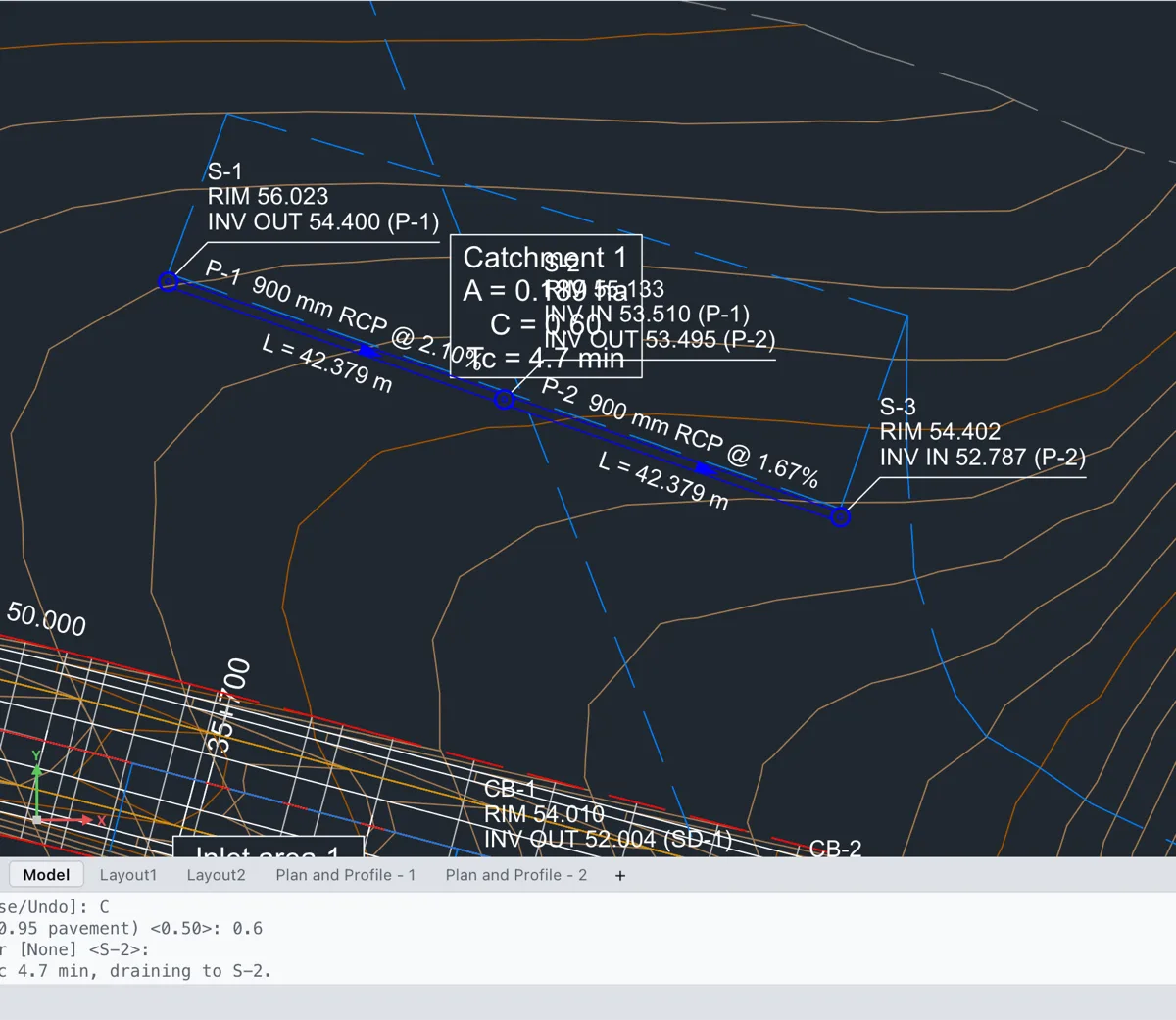
Terrace reports the catchment, for example Catchment 1: 0.1789 ha, C = 0.60, Tc 4.7 min, draining to S-2. In the plan it draws the boundary (layer C-STRM-CTCH), a hatch, a label with A, C and Tc, and the flow path used for Tc.
A catchment drawn by clicking, draining to S-2.
C and the time of concentration
The flow path runs from the boundary point farthest from the outlet down the surface to the outlet (the drained structure, or else the lowest boundary point). Its length and fall give Tc by the catchment's method, which you choose in Properties ▸ Time of concentration:
Method
Formula
Kirpich (default)
tc = 0.0195 L0.77 S−0.385 (minutes, L in m) — Kirpich (1940)
FAA
tc = 3.26 (1.1 − C) L0.5 / S1/3 (L in m, S in %) — FAA AC 150/5320-5
Kinematic wave
Sheet flow by HEC-22 Eq. 3-3 (n = 0.15, short grass), iterated with the rainfall intensity
Sheet + shallow + channel
Sheet flow for the first 100 m, then shallow concentrated flow (HEC-22 Eq. 3-4)
Given
A time you type in Given time (the sample's inlet areas use 5 min)
Slopes flatter than 0.1 % are taken as 0.1 % so the formulas stay finite. The catchment's C is the one you typed; the sample's inlet areas show an area-weighted C from two land uses (HEC-22 Eq. 3-2).
Catchment Properties: Name, Style, Area (read only), Runoff coefficient, Time of concentration (method), Given time (for Given), Time (the result, read only) and Drains to network. Select a catchment and drag its boundary grips to reshape it; the area, Tc and the network's flows follow.
Designing the pipes
Design Pipes sizes every pipe and sets every invert so the network carries its design flow within the rules.
Click Drainage ▸ Design Pipes, or type PIPEDESIGN (DESIGNPIPES, PDESIGN).
Pick the network (or press Enter for the one shown).
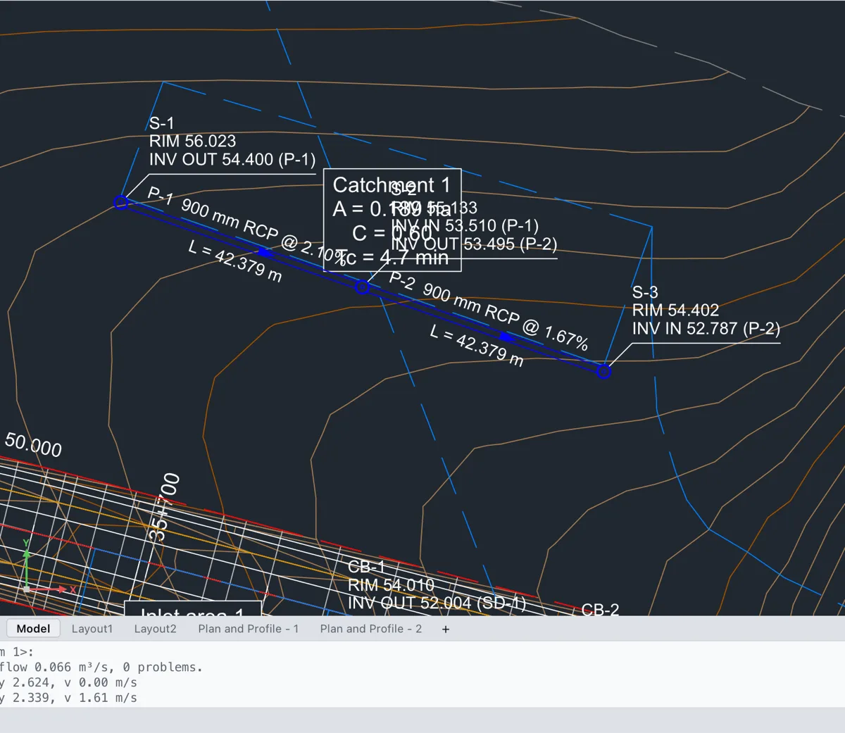
The command line lists every pipe with its size, flow Q (m³/s), full capacity and velocity, then the problems, if any:
The design of Storm 1: P-2 carries Catchment 1's 0.066 m³/s.
The rational method with PAGASA rainfall
Flows follow HEC-22 (3rd ed., 2009) Section 7.4, the storm drain computation sheet, pipe by pipe from the top of the network down:
ΣCA: the C × A of the catchments draining to the pipe's upper structure, plus the ΣCA of every pipe flowing into that structure.
Time: the longest of the inlet times and each upstream pipe's time plus its travel time (length ÷ velocity). The intensity is read at that time, but never less than the network's Inlet time (5 min by default).
Intensity i from the rainfall station's table at that duration and the Return period.
Q = ΣCA × i ÷ 360 (Q in m³/s, i in mm/h, A in ha), plus any known inflows carried down.
The DPWH standard carries the rainfall intensity-duration-frequency (RIDF) tables of 16 PAGASA stations: Port Area (Manila), Science Garden (Quezon City), Baguio, Mactan (Cebu), Davao, Iloilo, Tacloban, Legazpi, Cagayan de Oro, Dagupan, Zamboanga City, Tayabas, Aparri, Laoag, Tagbilaran and Virac, for durations of 10 minutes to 24 hours and return periods of 2 to 100 years (Science Garden to 500). Each table's source is listed in the standards editor (Standards and styles). If the network has no station, or the standard doesn't have it, the design notes it and takes the runoff as zero.
Sizing and inverts
Each pipe gets the smallest catalog size of its own shape and material (RCP stays RCP) that is at least the standard's minimum diameter and at least as big as every pipe flowing into it — sizes never shrink downstream — and that carries Q flowing no more than the Fullest flow depth (80 %), within its full capacity and the maximum velocity.
Where a pipe runs slower than the minimum velocity (not self-cleansing), Terrace steepens it, up to the maximum slope.
Inverts are set from the rules: minimum cover, minimum slope, and at each structure the outlet matched to the inlets (crowns, inverts, or a fixed drop).
At structures where the energy loss would back the water up over an incoming pipe's crown, the outlet pipe is dropped by the difference (HEC-22's crown drop, with the access hole loss coefficients of HEC-22 Table 7-5).
A pipe you have locked keeps its inverts (the sample's culvert is locked at the creek bed).
Hydraulic and energy grade lines
After sizing, Terrace runs the hydraulics from the outlet upstream, by HEC-22: normal depth and velocity in each pipe (Manning), the hydraulic grade line (HGL, the water surface) and the energy grade line (EGL, HGL plus the velocity head) along each pipe, and the losses at each structure. The water level at the outlet is the network's Tailwater: Free outfall, Normal depth, Critical depth or a Fixed elevation (for an outlet into a creek or a pond with a known flood level).
The flows and grade lines are refreshed whenever the ground, a catchment or the network's settings change. Sizes and inverts change only when you run Design Pipes.
What the problems mean
Problems show on the command line after a layout or design, in the network's Properties (with Zoom to), as a red dot in the Project browser, and as Fix 1 problem in Next step.
Message
Meaning and what to do
Pipe P-3: cover 0.45 m is less than the minimum 0.60 m
The pipe's top is too close to the ground somewhere along it. Lower the inverts (design again, or a deeper downstream structure), or lower the minimum cover if the standard allows.
… cover … at its start is more than the maximum …
The pipe is buried deeper than the maximum cover (6 m by default).
… slope … % is less than the minimum / more than the maximum …
The pipe is flatter than the minimum slope or steeper than the maximum (10 % by default).
Structure S-2: 2 outlet pipes (a gravity network needs one)
Water can only leave a structure one way. Take the run back with Undo and lay it out in the direction of flow.
Structure S-4: drop 0.85 m from P-3 is more than 0.60 m (drop manhole)
An incoming pipe enters more than the maximum drop above the outlet: a drop manhole is needed.
The outlet is higher than an incoming pipe: water would pond. Design again.
Pipe P-5: part of a loop (gravity networks must be trees)
Pipes close a ring. Lay the runs out again without the closing pipe.
Pipe P-2: flow … is more than its full capacity …
The pipe is too small for its flow.
Pipe P-2: surcharged (HGL above the crown)
The water surface is above the top of the pipe: the pipe flows under pressure.
Pipe P-2: velocity … is more than … / less than … (not self-cleansing)
Too fast (scour, abrasion) or too slow (silt settles). DPWH limits are 0.8 to 5 m/s.
Structure S-3: water level … above the rim (flooding)
The energy level at the structure is above its rim: water comes out of the inlet. Use bigger pipes, steeper slopes, or a lower tailwater.
Network …: no rainfall data for station … : runoff taken as zero
Choose a Rainfall station in Properties.
Network properties
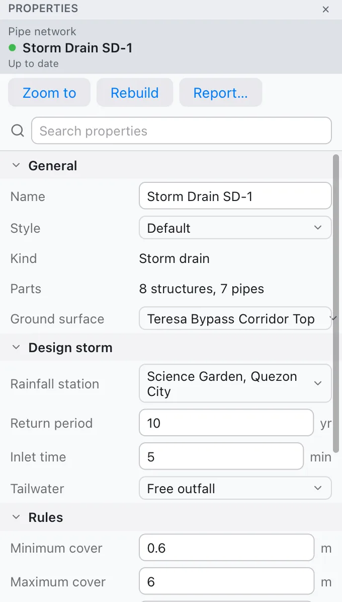
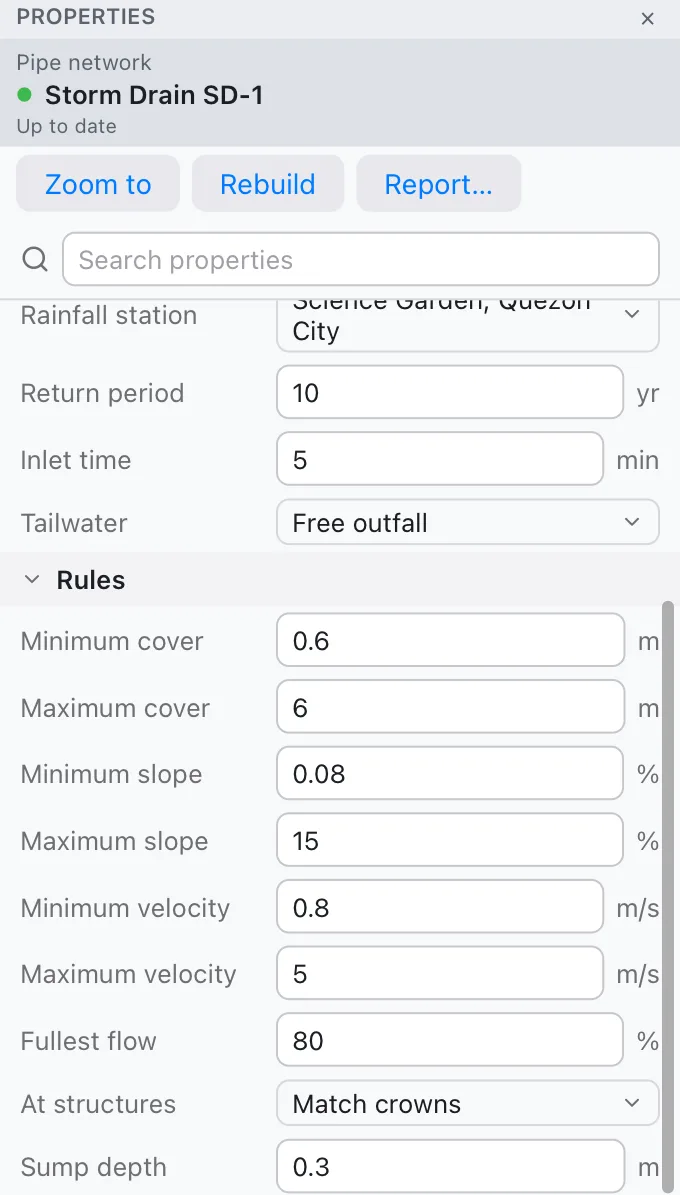
Select a network (click a pipe or structure, pick it in the Project browser under Pipe Networks, or find it with ⌘K) to see its settings:
General and Design storm.Rules (the sample allows 15 % for its steep outfall pipes).
Group
Rows
General
Name, Style, Kind and Parts (read only), Ground surface (for rims and cover — the corridor's Top surface for a drain under a new road).
Design storm
Rainfall station, Return period (years), Inlet time (minimum minutes), Tailwater and, for a fixed one, Tailwater elevation.
Rules
Minimum cover and Maximum cover; Minimum slope and Maximum slope (%); Minimum velocity and Maximum velocity; Fullest flow (% of the depth at design flow); At structures: Match crowns, Match inverts or Fixed drop (with Drop); Sump depth below the lowest invert.
The DPWH defaults come from DGCS 2015 Vol. 3 §6.4 (closed conduits): minimum pipe 910 mm, velocity 0.8 to 5 m/s, cover 600 mm. DPWH gives no minimum slope; 0.08 % is the slope at which a 910 mm pipe flowing full runs at 0.8 m/s. Change any rule and press Design Pipes again; each edit is one undo step.
Pipes in the profile view
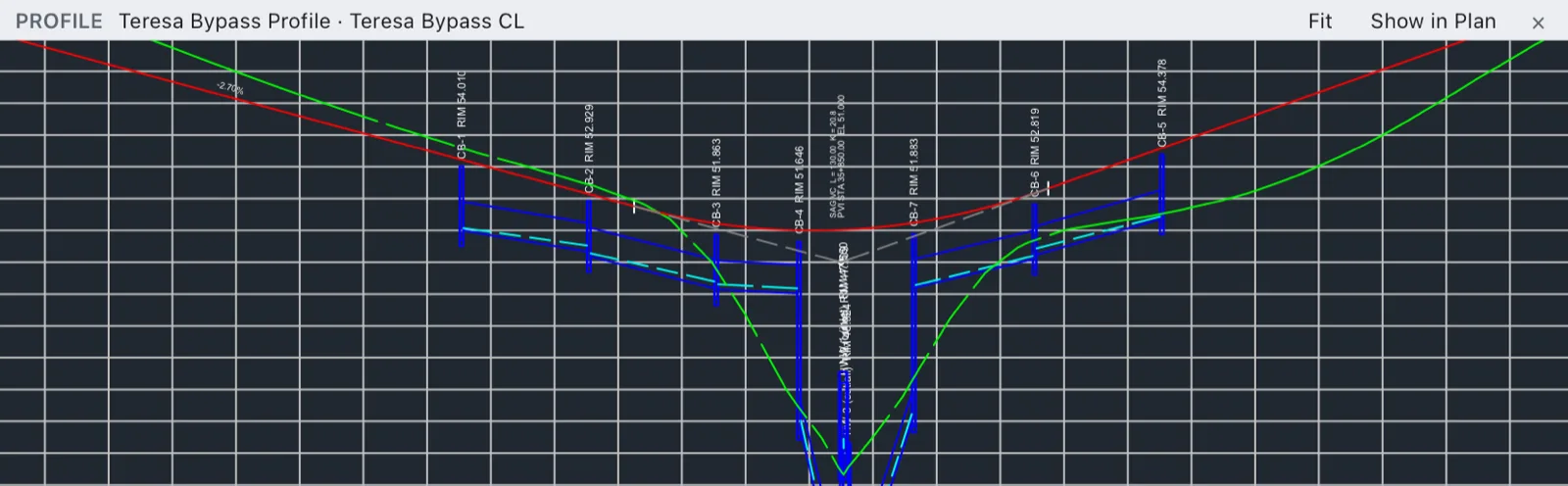
A profile view can show pipe networks along with the road: each structure from sump to rim with its name and rim, each pipe by its invert and crown, and the HGL. In the sample project both networks are shown in the Teresa Bypass profile view. Click Roads ▸ Show Under Plan to split the window and see it below the plan; zoom in on the sag with a pinch or the wheel.
Storm Drain SD-1 and Cross Drain CD-1 in the road's profile view.
Note In this version a network you create doesn't appear in a profile view, and there is no command or Properties row to add it yet. A network made with CREATENETWORK also has no alignment (and no Properties row sets one), so its reports leave Station and Offset empty; make the network with the dialog and choose Stations along to get them. The sample project's networks show both.
Pipe and structure reports
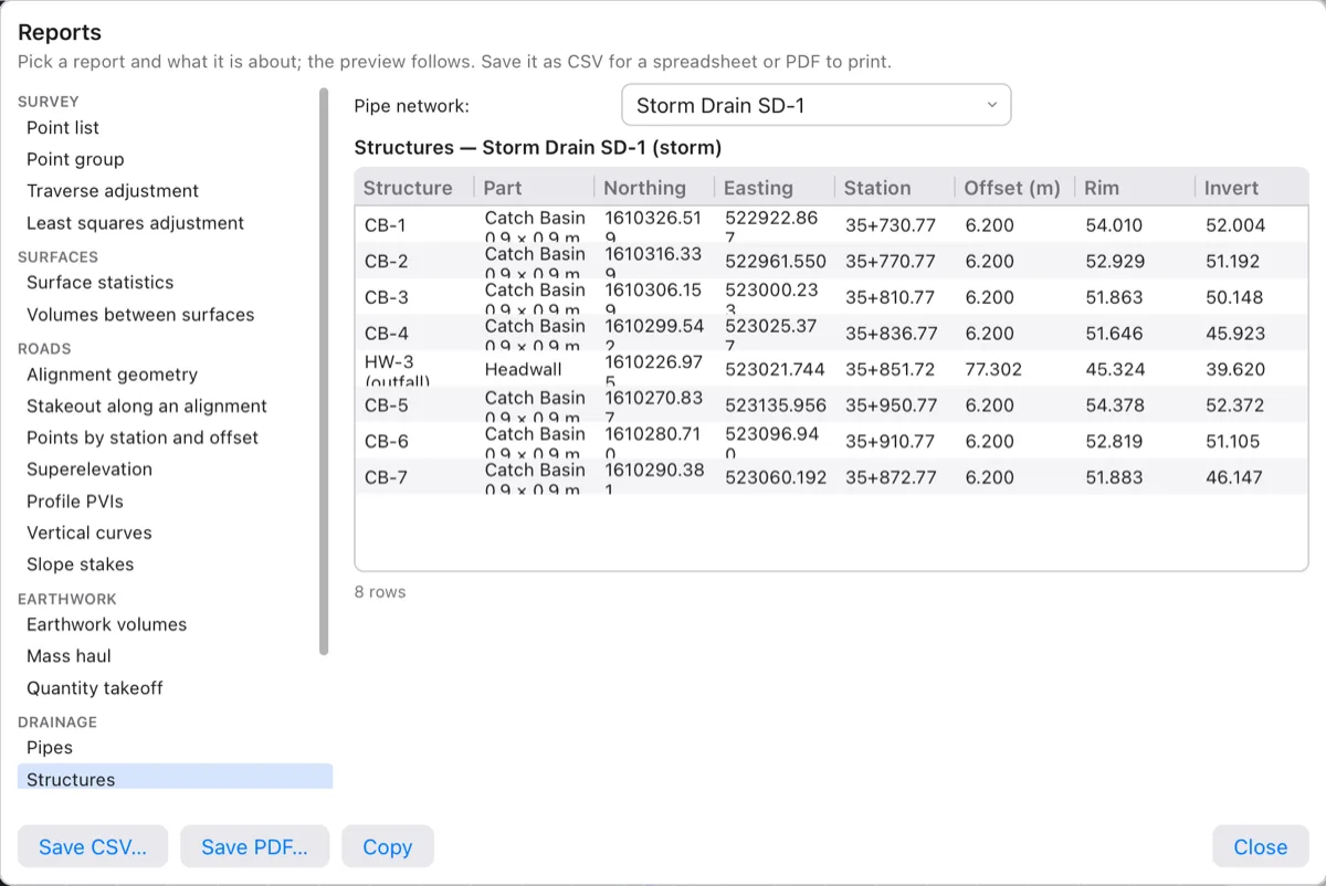
For a table of the whole network, type PIPEREPORT or STRUCTUREREPORT and pick the network, or use the Reports… dialog (Report… in the network's Properties, or ⌘K ▸ Reports). The quick commands print the table on the command line and open the Reports dialog, where you choose Drainage ▸ Pipes, Structures or Catchments and save CSV or PDF (see Reports).
The structures of Storm Drain SD-1.
Report
Columns
Pipes
Pipe, From, To, Size, Material, Length, Slope (%), Invert Up, Invert Down, Flow, Capacity, Velocity, Depth, HGL Up, HGL Down
Structures
Structure, Part, Northing, Easting, Station, Offset, Rim, Invert, Depth, Sump, HGL In, HGL Out
Catchments
Catchment, Area (ha), C, Tc (min), Tc Method, Drains To
Stations and offsets are measured along the network's alignment. In the sample, CB-1 sits at 35+730.77, 6.200 m right, rim 54.010, invert 52.004.
Water mains
A pressure network lays a water main at a constant cover below the ground, with fittings where it bends.
Click Drainage ▸ Pressure Network, or type PRESSURENETWORK (PRESSURE, WATERLINE).
At Network name, press Enter for Water 1 or type a name.
At Depth of cover over the pipe, press Enter for 1.00 m or type the cover.
Cover over the main.
Click the start of the main, then each bend; U takes back a point. Press Enter to finish.
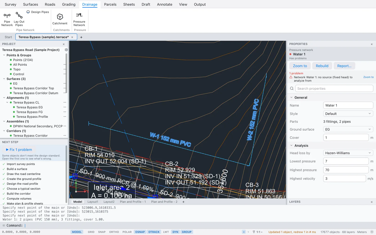
Terrace lays PVC 150 mm pipes (a common distribution size) with their centreline at cover + half the diameter below the ground, puts an elbow at every bend (the nearest standard angle: 11.25°, 22.5°, 45° or 90°) and a cap at each free end, and merges bends under 1°. A main that starts or ends on an existing fitting joins it, turning it into a tee or a cross. The command line sums it up, for example Water 1: 2 pipes (PVC 150 mm), 3 fittings, cover 1.00. Pipes are named W-1, W-2…, fittings F-1, F-2…, on layer C-WATR.
A water main and its Properties.
The pressure catalog has PVC (PN 10, 50–300 mm, Hazen-Williams C 150), ductile iron (K9, 100–600 mm, C 140), HDPE PE100 SDR 11 (63–400 mm OD, C 150) and steel (Sch 40, 150–600 mm, C 120). The labels show each pipe's inside diameter (152 mm for PVC 150).
Pressure network Properties: Name, Style, Parts, Ground surface, Cover; and for the analysis Head loss by (Hazen-Williams or Darcy-Weisbach), Lowest pressure and Highest pressure (as metres of water; DPWH/LWUA practice 7 to 70 m) and Highest velocity (3 m/s).
The analysis and its limits
Terrace solves a pressure network for the flow and velocity in each pipe, the head loss, and the head and pressure at each fitting, then checks them against the limits. The analysis needs at least one source (a fitting held at a fixed head, such as a reservoir or a connection to an existing main) and the demands at fittings. Terrace Free has no way to enter sources and demands, so a main you lay out reports Network Water 1: no source (fixed head) to analyze from and the analysis results stay empty: use the pressure network for layout, cover and fittings. Terrace Pro adds them — reservoirs, tanks, demands with daily patterns, pumps and valves — and analyses the network over a day the way EPANET does; see Water network analysis.
Good to know
Make the catchments before you design, or design again after adding them: Design Pipes sizes from the flows it finds at that moment.
For a drain under a new road, set the network's Ground surface to the corridor's Top surface so the rims follow the finished road.
Every drainage command is one undo step; edits in Properties are one each.
Catchments by delineation follow the surface's triangles: a good surface with breaklines along ditches and crowns (see Surfaces) gives better watersheds.