
Typical sections and corridors
This chapter shows how to turn a centerline and a design profile into a 3D road: first the typical section (an assembly), then the corridor that sweeps it along the alignment and daylights it to the ground. You'll be able to make a DPWH typical section in two clicks, change any lane, shoulder or slope, build and tune the corridor, and print slope stakes for the field.
How it fits together
A typical section is the road's cross section: lanes, shoulders (or curb, gutter and sidewalk), and the side slopes that run out to the ground. Terrace calls it an assembly. An assembly is made of subassemblies (parts): one part per lane, shoulder, curb or slope, each attached to the edge of the part inside it. The point where the assembly hangs from the centerline is its baseline point.
A corridor is the assembly swept along an alignment. At every section (every 10 m on tangents and 5 m on curves by default) Terrace places the assembly at the centerline's position and the design profile's elevation, tilts the lanes to the alignment's superelevation, and runs the side slopes until they meet the existing ground. The line where a side slope meets the ground is the daylight line. Joining the same point from section to section gives the corridor's feature lines (edge of travelled way, edge of shoulder, daylight…), and joining the top and bottom of the sections gives two surfaces: Top (finished grade) and Datum (the bottom of the pavement, for earthwork).
A corridor is built from four things: an alignment, its design profile, an assembly and a ground surface. Change any of them — drag a PI, move a PVI, widen a lane, re-survey the ground — and the corridor rebuilds by itself, followed by its surfaces, sample lines and volumes.
All the tools are on the Roads ribbon tab, in the Corridor group, and on the command line (see the Roads commands). Typical Section and Corridor open a dialog with every choice filled in; the typed commands ask the same questions one prompt at a time. Each command or dialog is one undo step.
The pictures use the sample project (Help ▸ Open the Sample Project): the Teresa Bypass Road, Km 35+200 to Km 36+422.77, with the typical section DPWH National Secondary, PCCP and the corridor Teresa Bypass Corridor. Point labels and TIN lines are turned off to keep the plan clear.
Tip The Next step panel offers Choose a typical section and Build the corridor as soon as the road has a design profile. Each button opens the same dialog as the ribbon.
Making a typical section
Start with a typical section from the design standard: Terrace fills in the lane and shoulder widths, the crown and shoulder slopes and the cut and fill slopes of the road class, so a DPWH section is right the first time. You can change every value afterwards.
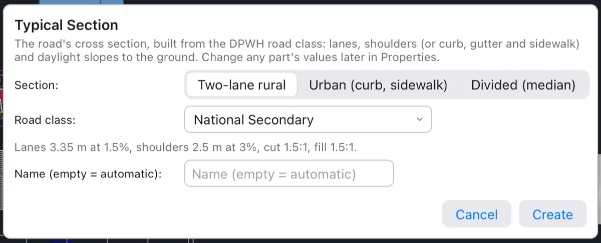
- Click Roads ▸ Typical Section (or Choose a typical section in Next step). The Typical Section dialog opens.
- Under Section, pick Two-lane rural (the default), Urban (curb, sidewalk) or Divided (median).
- Under Road class, pick the class from the project's standard. Terrace starts with the road class of the selected (or first) alignment; when no alignment has one, it takes the class whose rolling-terrain design speed is closest to 60 km/h (DPWH National Secondary). The line under the menu shows what that class gives: for National Secondary, Lanes 3.35 m at 1.5%, shoulders 2.5 m at 3%, cut 1.5:1, fill 1.5:1.
- Leave Name empty for an automatic name made from the kind and class, such as Two-lane rural (National Secondary), or type your own.
- Click Create.
Terrace makes the assembly and draws it beside the project, to the left of everything already drawn (you don't click a place). The command history and a short message say what was made, for example Typical section Urban (National Secondary): 8 parts. The assembly is drawn on the C-ROAD-ASSM layer at its baseline point, with its name under it, and is listed under Assemblies in the Project browser. Rename it in Properties at any time.
From the command line
Type CREATEASSEMBLY (CASSEMBLY, or TYPICALSECTION) to make the section by prompts and place it where you click.
- Terrace asks Typical section for National Secondary [Rural/Urban/Divided/Class/Dialog] <Rural>. The road class in the prompt is the one of your latest alignment that has one; with none, it's DPWH National Secondary (AASHTO: Rural Collector). Press Enter for a two-lane rural road, or type U (urban) or D (divided). Type DI to close the command and open the Typical Section dialog instead.
- To use another road class, type C first: Terrace lists the standard's classes in the command history and asks Road class. Type the name or its first letters (prov for Provincial) and press Enter; then choose rural, urban or divided.
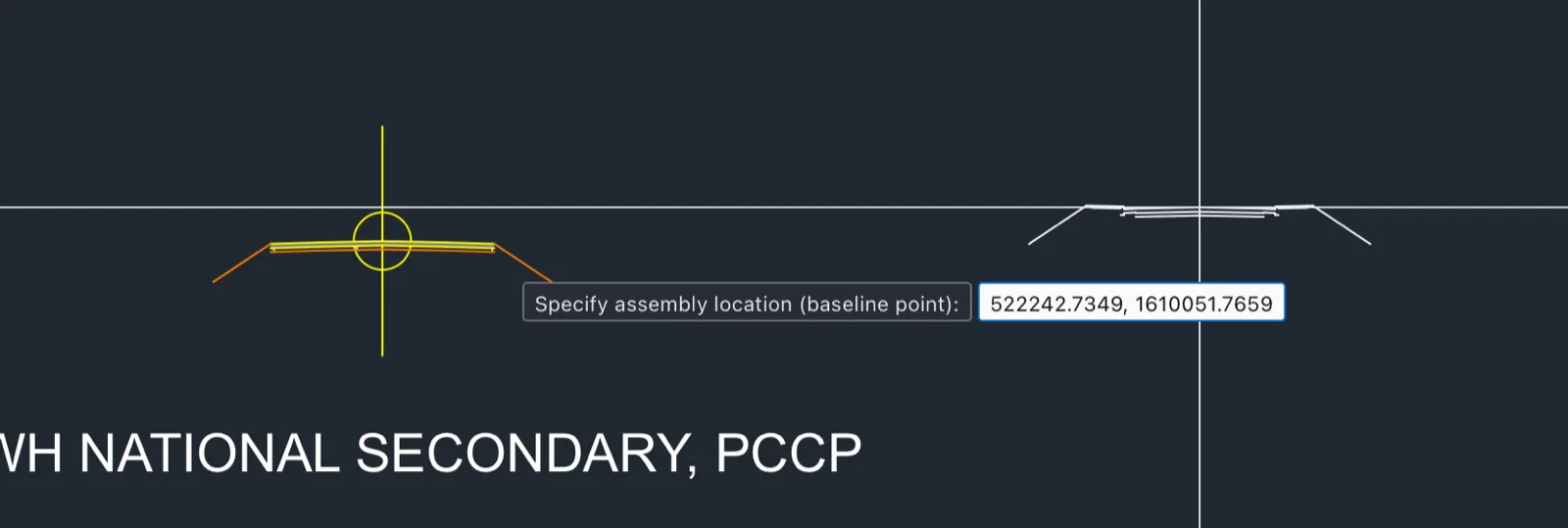
- At Specify assembly location (baseline point), move the cursor: the section's shape follows it. Click where you want it drawn — beside the plan, out of the way.
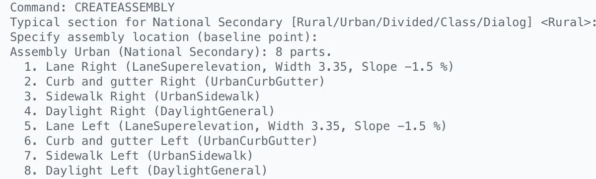
Terrace lists the new assembly's parts in the command history, with each lane's width and slope:
The three kinds
| Kind | Parts on each side, from the centerline out |
|---|---|
| Two-lane rural (default) | Lane (LaneSuperelevation), shoulder (ShoulderExtend, paved), side slope with a ditch in cut (BasicSideSlopeCutDitch). Six parts. |
| Urban | Lane, curb and gutter (UrbanCurbGutter), sidewalk (UrbanSidewalk), daylight slope (DaylightGeneral). Eight parts. |
| Divided | A depressed median (MedianDepressed, 6.0 m wide) on the centerline, then on each side an inner lane, an outer lane (LaneOutsideSuper), a shoulder and a side slope. Nine parts. |
What comes from the road class: lane width, shoulder width, cross slope of the lanes (falling away from the crown), shoulder slope, and the cut and fill slopes. What comes from the standard: the pavement. A DPWH section gets 230 mm Portland cement concrete pavement (PCCP) on 200 mm aggregate subbase (DPWH Items 311 and 200); an AASHTO section gets two 50 mm asphalt layers on 150 mm base and 200 mm subbase.
| DPWH road class | Lane | Shoulder | Crown | Shoulder slope | Cut / fill |
|---|---|---|---|---|---|
| Expressway | 3.65 m | 3.00 m | 1.5 % | 3 % | 1.5:1 |
| National Primary | 3.35 m | 3.00 m | 1.5 % | 3 % | 1.5:1 |
| National Secondary | 3.35 m | 2.50 m | 1.5 % | 3 % | 1.5:1 |
| National Tertiary | 3.35 m | 1.50 m | 1.5 % | 3 % | 1.5:1 |
| Provincial, City/Municipal | 3.05 m | 1.00 m | 1.5 % | 3 % | 1.5:1 |
| Barangay | 2.00 m | 0.50 m | 1.5 % | 3 % | 1.5:1 |
| Tourism, Farm-to-Market | 3.05 m | 1.50 m | 1.5 % | 3 % | 1.5:1 |
These are the built-in values; your project's standard may differ if someone edited it (see Standards and styles). Side slopes are written run:rise, so 1.5:1 is 1.5 m across for every 1 m up or down.
Note The two-lane rural section uses ShoulderExtend for its shoulders with the lane's pavement layers, so DPWH shoulders come out as PCCP too, as in the sample project. To make a shoulder unpaved, turn off its Paved switch in Properties (it keeps the base and subbase layers only).
Changing a typical section
Select the assembly — click its drawing, or its name in the Project browser — and the Properties panel lists every part with its values, one group per part. Change a value and press Enter: the assembly redraws and every corridor built with it rebuilds. Each change is one undo step.
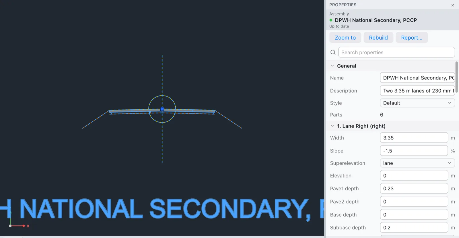
At the top are Name, Description, Style and the number of Parts. Then each part, titled with its number, name and side (1. Lane Right (right)). The rows depend on the part's kind:
- Lengths (widths, depths, offsets) in project units, such as Width 3.35 m.
- Slopes and grades in percent, measured going outward from the attachment point: −1.5 % falls away from the road, +2 % rises.
- Side slope ratios as (run : 1): 1.5 means 1.5:1.
- Choices, such as Superelevation (lane or none).
- Switches, such as Paved on a shoulder.
- Text, such as the material names used for quantities (Pave1 material: Portland Cement Concrete Pavement).
What each value means is in the catalog below. Use the search box at the top of the panel to find a row quickly (type cut to see every cut slope).
Adding a part
To add a barrier, a ditch, a wall or any other part, use ADDSUBASSEMBLY (SUBASSEMBLY), on Roads ▸ Add Subassembly.
- At Select assembly, press Enter for the selected (or latest) assembly, click another one, or type its name.
- At Subassembly kind (? for the list), type the kind, such as BarrierJersey. The first letters are enough (DitchV), and case doesn't matter. Type ? (or press Enter) to list every kind by category. Terrace prints the kind's description.
- At Side [Right/Left/Both/None], press Enter for both sides, or type R or L. N (the default for medians) centers the part on the baseline point.
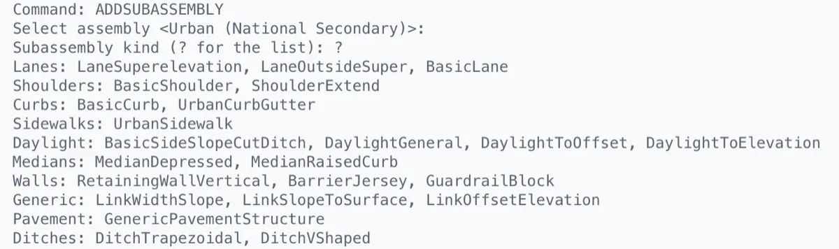
The new part is attached to the outermost part on that side and named after its kind and side (GuardrailBlock Right):

Watch out Parts are only ever added at the outside. On a section made by CREATEASSEMBLY the outermost part is the side slope, so a part you add lands beyond the daylight line. There's no command yet to insert a part between two others or to move a part. To build a different arrangement, start from the typical section closest to it and change the parts' values in Properties.
The subassembly catalog
Every part is one of 23 kinds. All of them follow the same rules: they're built outward from the point they're attached to (to the right for right parts, to the left for left parts); "slope" values are rise/run going outward; "ratio" values are side slopes run:rise. Parts with layers make shapes (pavement, base, subbase, curb…) that are measured for quantities; the material text of each shape names the pay item (see DPWH pay items).
| Kind | Category | What it is | Main parameters (defaults) |
|---|---|---|---|
LaneSuperelevation | Lanes | A travel lane with up to four layers. Its cross slope follows the alignment's superelevation on its side. | Width 3.35, Slope −2 %, Superelevation lane/none, Pave1/Pave2/Base/Subbase depth 0.05/0/0.15/0.20, their materials. |
LaneOutsideSuper | Lanes | An outer lane hung from another lane's edge, same layers, also superelevated. | As LaneSuperelevation. |
BasicLane | Lanes | A lane of one depth (one pavement shape). | Width 3.5, Depth 0.20, Slope −2 %, Superelevation, Material. |
BasicShoulder | Shoulders | A shoulder of one depth. | Width 2.5, Depth 0.20, Slope −4 %, Superelevation breakover/lane/none, MaxBreakover 8 %, Material. |
ShoulderExtend | Shoulders | A shoulder with the lane's layers, paved or unpaved (base and subbase only). | Width 2.5, Slope −3 %, Superelevation, MaxBreakover 8 %, Paved on/off, layer depths and materials. |
BasicCurb | Curbs | A rectangular curb, top level with its attachment. | Width 0.15, Depth 0.45, Material. |
UrbanCurbGutter | Curbs | Curb and gutter: gutter falling to the curb face, the face, then the curb top. | GutterWidth 0.6, GutterSlope −6 %, CurbHeight 0.15, FaceBatter 0.025, CurbWidth 0.15, Depth 0.45, GutterDepth 0.20. |
UrbanSidewalk | Sidewalks | A sidewalk with grass strips before and behind it. | InnerBuffer 0, Width 1.5, OuterBuffer 0.3, Slope +2 %, Depth 0.10. |
BasicSideSlopeCutDitch | Daylight | In fill, a slope down to the ground; in cut, a ditch, then a slope up to the ground. | CutSlope 2:1, FillSlope 4:1, ForeslopeRatio 4:1, DitchDepth 0.6, BottomWidth 1.2, MaxRun 200, FallbackRun 3. |
DaylightGeneral | Daylight | Cut or fill slope to the ground, steeper as it gets deeper (three tiers), with optional benches. | CutSlope1/2/3 2:1, 1.5:1, 1:1 up to CutDepth1/2 1.5 / 5.0; FillSlope1/2/3 4:1, 2:1, 1.5:1 up to FillDepth1/2 1.5 / 6.0; Cut/FillBenchHeight 0 (none), BenchWidth 2.0, BenchSlope −4 %. |
DaylightToOffset | Daylight | One link at a slope out to an offset from the centerline. | Offset 10, Slope −50 %. |
DaylightToElevation | Daylight | A side slope up or down to an elevation. | Elevation 0 (relative), Ratio 2:1. |
MedianDepressed | Medians | A depressed median centered on its attachment: edges, slopes, flat bottom. | Width 6.0, Depth 0.5, BottomWidth 1.0. |
MedianRaisedCurb | Medians | A raised concrete median centered on its attachment. | Width 1.2, Height 0.15, FaceBatter 0.025, Depth 0.3. |
RetainingWallVertical | Walls | A vertical wall down to (fill) or up to (cut) the ground, with a footing. | Thickness 0.3, FootingDepth 0.6, DefaultHeight 2.0. |
BarrierJersey | Walls | A New Jersey concrete barrier standing on its attachment. | Height 0.81, BaseWidth 0.61, TopWidth 0.15. |
GuardrailBlock | Walls | A guardrail post with block-out — a marker only; it doesn't extend the section. | Offset 0.6, Height 0.7, PostWidth 0.15. |
LinkWidthSlope | Generic | One link of a width and slope. | Width 1.0, Slope −2 %, PointCodes, LinkCodes. |
LinkSlopeToSurface | Generic | One link at a slope until it meets the ground. | Slope −50 %, MaxRun 200, FallbackRun 3. |
LinkOffsetElevation | Generic | One link to a point at an offset and a height from the baseline point. | Offset 5, Elevation 0. |
GenericPavementStructure | Pavement | A pavement block with its own shape code and material. | Width 3.0, Slope −2 %, Depth 0.20, ShapeCode Pave1, Material Asphalt. |
DitchTrapezoidal | Ditches | A trapezoidal ditch: foreslope, bottom, back slope up to the attachment's level. | ForeslopeRatio 3:1, Depth 0.6, BottomWidth 1.0, BackslopeRatio 3:1. |
DitchVShaped | Ditches | A V ditch: foreslope down to the flowline, back slope up. | ForeslopeRatio 4:1, Depth 0.5, BackslopeRatio 4:1. |
The defaults above are the catalog's; parts made by CREATEASSEMBLY take their widths, slopes and pavement from the road class and standard instead. The daylight kinds and the wall have a Surface switch that the corridor's target sets for you, MaxRun (how far out to look for the ground) and FallbackRun (how far the fill slope is drawn when there's no ground to reach).
Building the corridor
Once the road has a design profile and a typical section, build the corridor. Terrace fills in the obvious answer for every choice, so on a simple project it's one click on Create.
- Click Roads ▸ Corridor (or Build the corridor in Next step). It's also on the Alignment contextual tab when a centerline is selected. The New Corridor dialog opens on the selected alignment (or the one the selected profile or profile view belongs to; else the first).
- Check the fields (table below) and change what you need.
- Click Create.
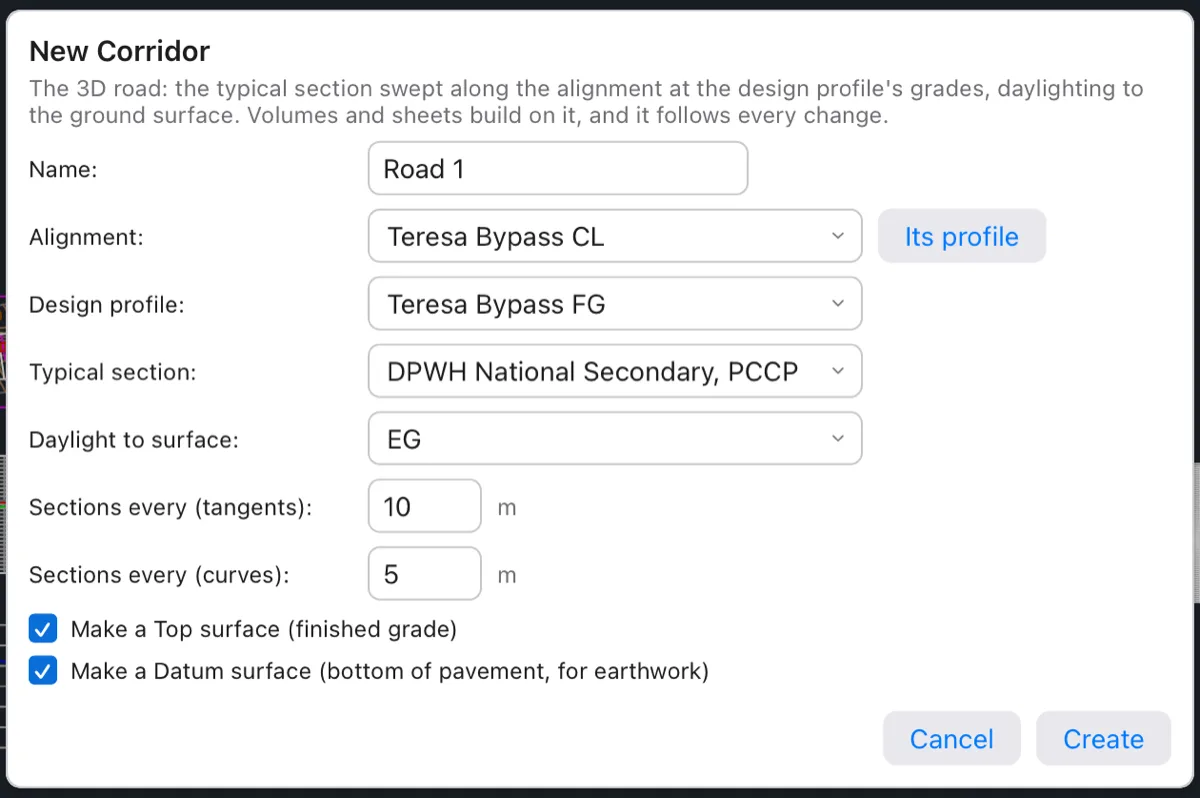
| Field | What it does (default) |
|---|---|
| Name | The corridor's name: Road 1, or Road 2… if that's taken. It must be new. |
| Alignment | The baseline: the road's centerline. Its profile sets Design profile back to that alignment's design profile after you change the alignment. |
| Design profile | The alignment's design profile (the latest one made). If the alignment has none, the dialog says so in orange and Create asks you to make one first (Design Profile). |
| Typical section | The selected (or first) assembly. |
| Daylight to surface | The ground the side slopes run out to: the surface called EG, else the first surface. Choose (none) to draw the slopes a fixed distance (FallbackRun). |
| Sections every (tangents) | Section spacing on tangents: 10 m (25 ft in US units). |
| Sections every (curves) | Section spacing on horizontal curves, spirals and vertical curves: 5 m (10 ft). |
| Make a Top surface (finished grade), Make a Datum surface (bottom of pavement, for earthwork) | Which corridor surfaces to make. Both are ticked; keep the Datum for earthwork. |
Terrace builds the corridor at once and says how many sections it has, for example Corridor Road 1: 204 sections. (with the number of notes, if some sections had a problem). Create refuses, with a note at the bottom of the dialog, when the alignment has no design profile, there's no typical section yet, or the name is empty or already used.
From the command line
Type CREATECORRIDOR (CCORRIDOR, or CORRIDOR) to answer the same questions one prompt at a time; Enter takes each default, so it's the command and five presses of Enter.
- Select baseline alignment [Dialog]: Enter for the selected (or latest) alignment, or click one, or type its name. Type D to open the New Corridor dialog instead. If the alignment has no design profile yet, Terrace says so and stops — draw one first with
DRAWPROFILE(see Profiles). - Select design profile: Enter for the alignment's design profile. A profile of another alignment is refused.
- Select assembly: Enter for the selected (or latest) typical section. With no assembly at all, Terrace asks you to make one first.
- Select target surface for daylighting [None]: Enter for the existing ground (the surface called EG or Existing…, else the first surface that isn't a corridor's). Type N for none: side slopes are then drawn a fixed distance (FallbackRun).
- Section frequency on tangents (half on curves): Enter for 10 m (25 ft in US units), or type another distance.

The command always makes both the Top and the Datum surface.
What you get:
- A corridor named Road 1 (Road 2… for the next ones; rename it in Properties) with one baseline and one region, Region 1. Sections are built from the start to the end of the design profile within the alignment.
- Sections every 10 m on tangents and every 5 m on curves, spirals and vertical curves, plus one at every geometry point (TS, SC, PC, PVI…) and every superelevation change.
- Feature lines along the section points, drawn on
C-ROAD-CORR, and the section lines onC-ROAD-CORR-SCTN. - Two new surfaces, Road 1 Top and Road 1 Datum (those you ticked, in the dialog), listed under Surfaces.
- A summary in the command history; and, if some sections had a problem, up to six notes such as daylight not reaching the ground, with the rest in Properties.
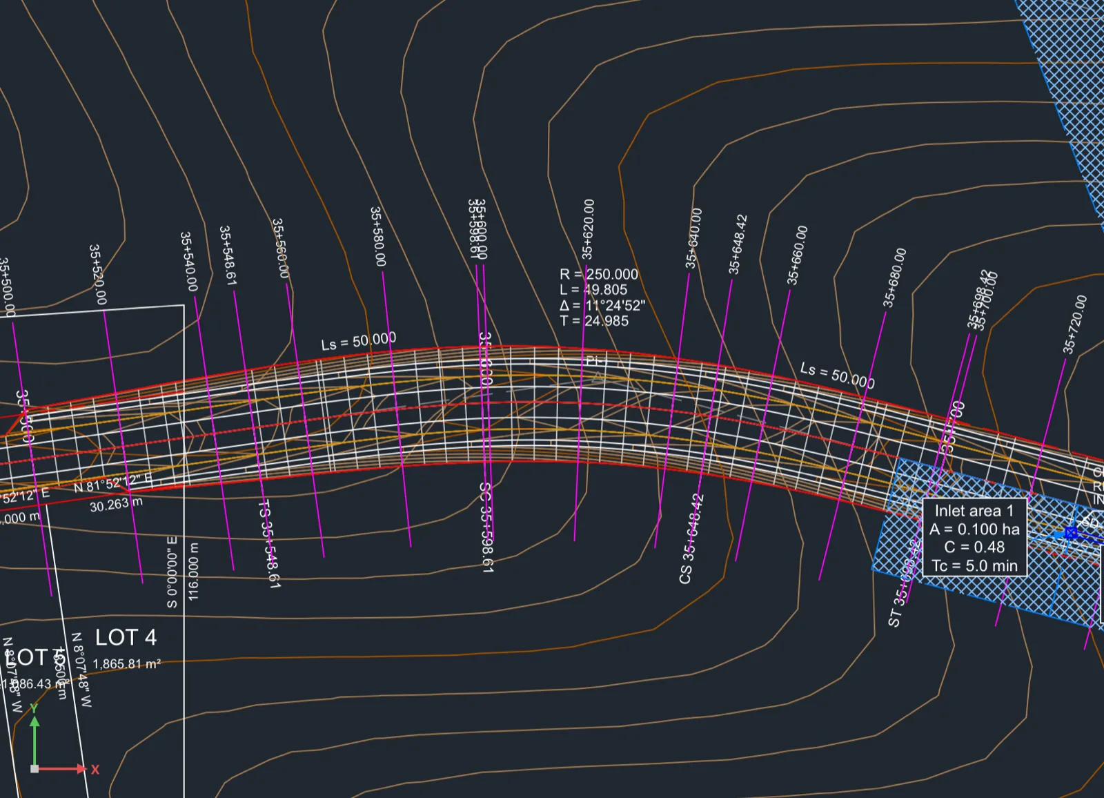
Tip The corridor follows the design profile, not the whole alignment: if the profile starts at 35+200 and ends at 36+422.77, so does the corridor. Lengthen the profile to lengthen the road.
Daylighting and targets
A target is another object a part follows. When you choose a daylight surface, the New Corridor dialog (and CREATECORRIDOR) makes every part that can reach a surface — the side slopes, DaylightGeneral, LinkSlopeToSurface, the retaining wall — target that surface. At each section Terrace then:
- decides whether the section is in cut or fill at the hinge (the outer edge of the shoulder);
- in fill, runs the fill slope down until it meets the ground; in cut, builds the ditch (for
BasicSideSlopeCutDitch) and runs the cut slope up to the ground; - for
DaylightGeneral, picks the slope by depth — flatter for shallow cuts and fills, steeper for deep ones — and adds benches every CutBenchHeight / FillBenchHeight if you set them; - gives up after MaxRun (200 m) and writes a note naming the station and side.
The point where the slope meets the ground is coded Daylight (and Daylight_Cut or Daylight_Fill), so it becomes a feature line in plan and a row in the slope stake report.
Note The catalog also has width, offset and elevation targets — a lane's Width can follow an offset alignment or polyline, an Elevation can follow a profile — and the corridor engine honours them, but this version of Terrace has no command, dialog or panel to set them. Only the surface target is set, by the New Corridor dialog or CREATECORRIDOR. Corridor Properties doesn't show a region's targets, and there's no way yet to add a second region or baseline.
Superelevation in the corridor
You don't set superelevation in the corridor: it comes from the alignment. When the alignment has superelevation (computed from the standard's emax and the design speed — see Alignments), each lane whose Superelevation is lane takes the cross slope of its side at every station: normal crown on tangents, rotating through the runout and runoff, full superelevation on the curve.
Shoulders follow one of three rules (their Superelevation row):
- breakover (the default): on the low side of the curve the shoulder is never flatter than the lane; on the high side it keeps its own slope as long as the difference from the lane (the rollover) stays within MaxBreakover, 8 %.
- lane: the shoulder takes the lane's slope.
- none: the shoulder keeps its own Slope.
Set a lane to none to keep its own Slope everywhere (a one-way ramp lane, for instance). Because each region adds a section at every superelevation change (At superelevation points), the transitions are modelled exactly, not just at the 5 m and 10 m stations.
Corridor properties
Select the corridor in the plan or the Project browser. The Corridor contextual tab appears on the ribbon (Rebuild, Sample Lines, Volumes, and Properties, Zoom To, Report), and the Properties panel shows:
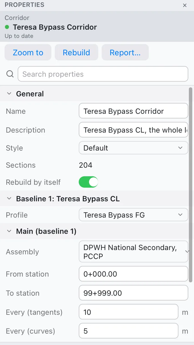
| Row | What it does |
|---|---|
| Name, Description, Style | The corridor's name, a note, and how it's drawn (a style from the list, such as Feature Lines Only, which hides the section lines). |
| Sections | How many sections were built. |
| Rebuild by itself | On (default): the corridor rebuilds after every change it depends on. Off: it waits for Rebuild — useful on a long road while you make many edits. |
| Baseline 1: alignment ▸ Profile | The design profile the baseline follows; choose another profile of the same alignment to try an alternative. |
| Assembly | The typical section used in this region. |
| From station, To station | Where the region starts and ends (clipped to the profile). |
| Every (tangents), (curves), (spirals), (vertical curves) | The section frequency on each kind of geometry. |
| At geometry points, At superelevation points | Extra sections at TS, SC, PC, PVI… and at every superelevation change. |
Below the rows, the panel lists the corridor's problems in plain words (for example daylight that didn't reach the ground at a station), each with Zoom to. The Project browser shows a green dot for an up-to-date corridor, and another colour when it's waiting for a rebuild or has problems.
Rebuilding
Normally you never rebuild by hand: after each command Terrace rebuilds what changed and everything downstream, and the status bar says what it did (Updated 3 objects, redraw 3 in 12 ms). Rebuild yourself when:
- the corridor's Rebuild by itself is off: click Rebuild in Properties or on the Corridor tab, or type
CIVILREBUILD(CRB) with the corridor selected; - you want everything brought up to date at once:
CIVILUPDATE(CUP), also Sheets ▸ Update Now.
See Selecting and editing for how live updates work.
Intersections
Terrace's corridor engine knows how to build an intersection of two roads — curb return alignments and profiles, and regions split so the crossing is built from the main road's crown and the side road's edge — but this version has no command or dialog for it, and the New Corridor dialog and CREATECORRIDOR make a corridor with a single baseline. For now, model an intersection with:
- a corridor for each road;
- curb returns drawn with
CURBRETURN(Roads ▸ Curb Return, see Alignments); - the corner areas graded with feature lines (see Grading).
The slope stake report
Slope stakes are what the survey crew sets out: at each station, the offset and elevation of the edge of pavement, the shoulder and the catch point where the slope meets the ground. Select the corridor and click Report… in Properties (or Corridor ▸ Report); the Reports dialog opens on Slope stakes.
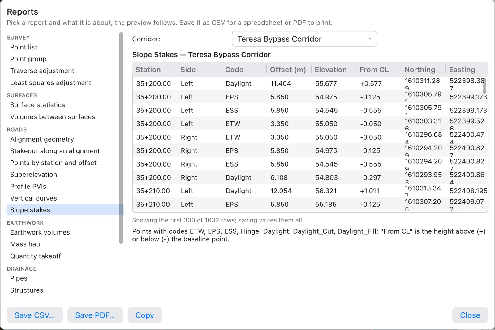
Each row is one point: Station, Side (Left, Right or CL), Code, Offset from the centerline, Elevation, From CL (height above + or below − the centerline point) and the point's Northing and Easting. The codes reported are ETW (edge of travelled way), EPS (edge of paved shoulder), ESS (edge of subgrade shoulder), Hinge and Daylight (with Daylight_Cut / Daylight_Fill). Save it with Save CSV… or Save PDF…, or Copy it; see Reports for everything the dialog does.