Getting started
This chapter shows you around the start page, makes your first project, opens the finished sample road and starts the built-in tutorial. By the end you'll have taken a road from survey points to plan-and-profile sheets, and you'll know which chapter to read next for each step.
Installing Terrace
Terrace runs on a Mac with Apple silicon (M1 or later) and macOS 11 or later, and on 64-bit Windows 10 and 11.
On a Mac
- Download the Mac installer from the download section of the website.
- Open it and follow its steps. Terrace goes in your Applications folder.
- Open Terrace from Applications or Launchpad.
On Windows
- Download the Windows installer from the download section.
- Run it. Terrace for Windows isn't code-signed yet, so the first time Windows SmartScreen says it's from an unknown publisher: click More info, then Run anyway. It installs for you alone, so no administrator rights are needed.
- Open Terrace from the Start menu. To remove it, use Settings ▸ Apps.
This guide writes shortcuts the Mac way. On Windows, press Ctrl where it says ⌘, and Alt for ⌥.
Terrace keeps itself up to date. Once a day it looks for a newer version, downloads it quietly, and installs it when you quit. Help ▸ Check for Updates… looks right away. To be asked first, uncheck Help ▸ Install Updates Automatically; to stop looking, uncheck Help ▸ Check for Updates Automatically. Help ▸ What's New lists what each version changed.
Terrace is free. Terrace Pro adds four ribbon tabs of tools for a design office.
The start page
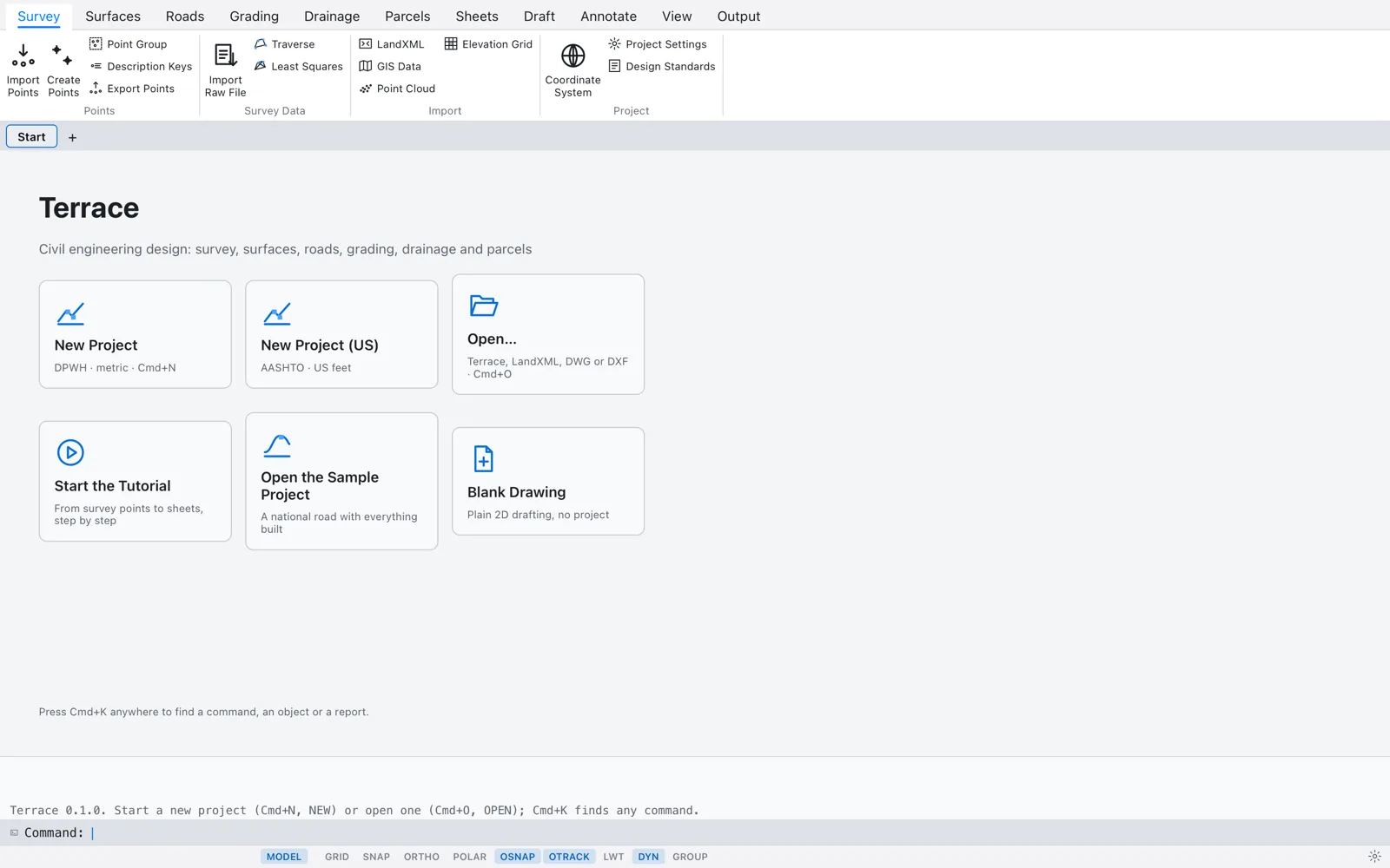
When Terrace opens, it shows the Start tab. Everything a new user needs is one click away from here. The ribbon above it already works: a click on any civil button with no project open first makes a new project for you, then opens the button's dialog or starts its command.
The six cards
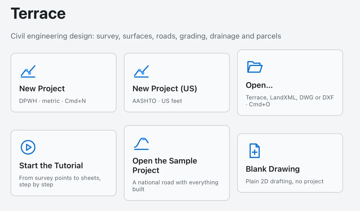
| Card | What it does |
|---|---|
| New Project | A new, empty civil project that follows the DPWH design standards in metric units. Same as File ▸ New Project or ⌘N. |
| New Project (US) | A new project that follows AASHTO in US survey feet. |
| Open… | Opens a Terrace project (.terrace), a LandXML file (.xml, imported into a project), or a .dwg / .dxf drawing. Same as ⌘O. |
| Start the Tutorial | A guided tour in ten steps, from survey points to sheets, in a project of its own. See The built-in tutorial. |
| Open the Sample Project | The Teresa Bypass Road, a finished national road project with every kind of object built. See The sample project. |
| Blank Drawing | A plain 2D drawing with no civil project settings, for drafting only. Terrace switches to the Draft tab. See Drafting. |
Under the cards, Recent Documents lists the last ten files you opened or saved; click one to open it again. It appears once you have opened something. At the bottom, a reminder: ⌘K anywhere opens the command palette to find any command, object or report.
Creating a project
A project holds all the civil objects of one job: points, surfaces, alignments, profiles, corridors, pipe networks, parcels and sheets. Start one before you import anything.
- Click New Project on the start page (or press ⌘N). For a job in US units, click New Project (US) instead.
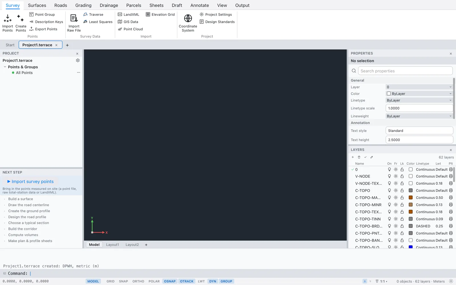
- A tab named Project1.terrace opens on the Survey ribbon tab, and the command line says
Project1.terrace created: DPWH, metric (m). - Save it once with ⌘S to give it a name and a folder. See Saving.
DPWH metric or AASHTO US
The standard decides the defaults Terrace fills in for you: design speeds and road classes, minimum curve radii and superelevation, K values for vertical curves, and the typical sections offered for corridors. With DPWH, a new centerline gets 60 km/h and the DPWH tables; with AASHTO US, distances are in US survey feet and the AASHTO tables apply.
- File ▸ New Project With offers three choices: DPWH (metric), AASHTO (metric) and AASHTO (US feet).
- Terrace remembers the last standard you chose. ⌘N, the + at the end of the drawing tabs and the ribbon buttons all make a new project with it.
- An empty metric project shows about a kilometre of plan; a US one about 3,000 ft.
- You can change the standard later in Project Settings, and edit every table in Standards and styles.
The sample project
The quickest way to see what Terrace does is to open the finished sample: the Teresa Bypass Road, a 1.2 km two-lane national secondary road at Km 35+200 in Teresa, Rizal, designed for 60 km/h. It is built from scratch when you open it, so it needs no files.
- Click Open the Sample Project on the start page, or choose Help ▸ Open the Sample Project.
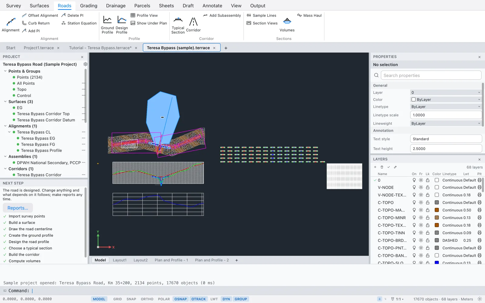
- A card says Building the sample project… for a moment. Then a tab named Teresa Bypass (sample).terrace opens on the Roads tab, zoomed to show everything.
A short tour
Everything in the sample is listed in the Project browser on the left. Here is what's there and where to read about it:
| In the browser | What it is | Chapter |
|---|---|---|
| Points (2134), All Points, Topo, Control | The topographic survey: ground, creek and tree shots in PRS92 zone 3, and the control points, in point groups. | Survey and points |
| EG, Teresa Bypass Corridor Top, Teresa Bypass Corridor Datum | The existing ground surface, and the finished road and subgrade surfaces the corridor makes. | Surfaces |
| Teresa Bypass CL | The road centerline: 1,222.772 m, stations 35+200.00 to 36+422.77, four PIs with spiral curves. | Alignments |
| Teresa Bypass EG, Teresa Bypass FG, Teresa Bypass Profile | The ground profile, the finished-grade (design) profile and the profile view they're drawn in. | Profiles |
| DPWH National Secondary, PCCP | The typical section (an assembly): two 3.35 m PCCP lanes, shoulders and side slopes. | Typical sections and corridors |
| Teresa Bypass Corridor | The 3D road, built from the centerline, the FG profile and the typical section, daylighting to EG. | Typical sections and corridors |
| Teresa Bypass Sections | Sample lines across the road, with section views, cut and fill and the mass haul. | Sections and earthwork |
| Cross Drain CD-1, Storm Drain SD-1, the catchments | The RCP cross drain under the creek and the storm drain, with eight catchments. | Drainage and water |
| San Roque Lots (14) | Lots along the road, with technical descriptions. | Parcels |
| Plan and Profile | View frames along the road; the sheets are the Plan and Profile - 1 and - 2 layout tabs under the plan. | Sheets and plotting |
Try these to get a feel for it:
- Click an object in the browser. It's selected in the plan, its fields show in Properties on the right, and a contextual ribbon tab for it may open. Double-click it to zoom to it.
- Zoom to the road. Click Teresa Bypass Corridor, then Zoom To on the Corridor tab that opens.
- See a sheet. Click the Plan and Profile - 1 tab under the plan.
- Show the profile under the plan. Roads ▸ Show Under Plan. See The profile pane.
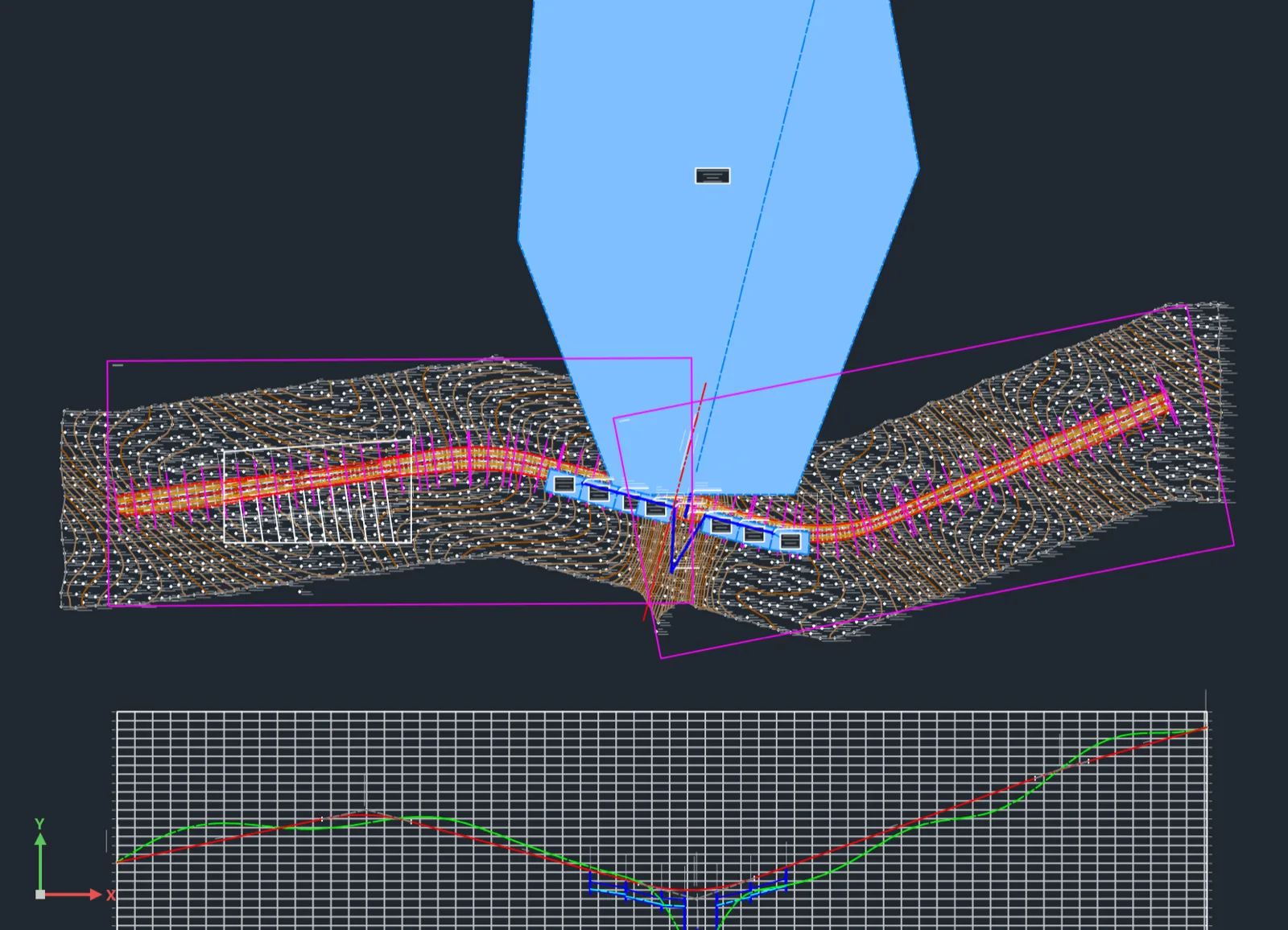
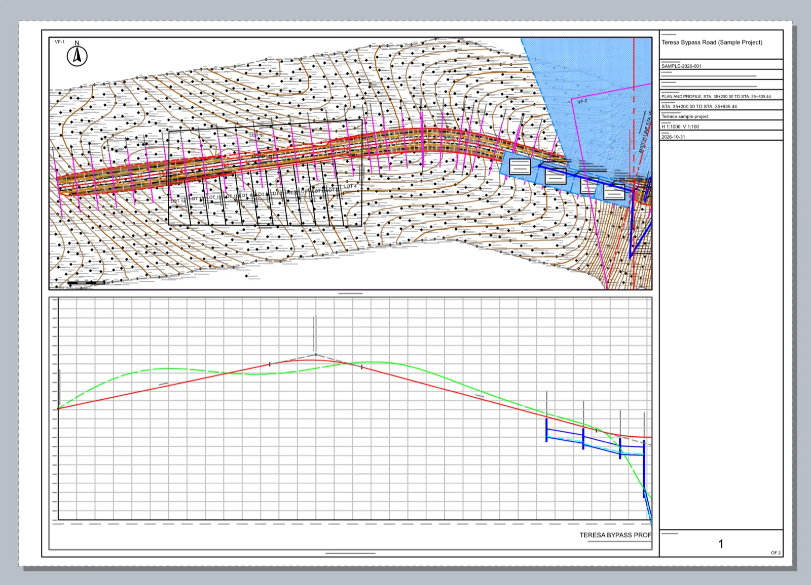
Tip The sample is a normal project. Change anything you like — drag a PI, change the design speed — and watch what depends on it follow. Nothing is saved until you save it, and ⌘Z undoes each change.
The built-in tutorial
The tutorial walks you through a whole road on the same Teresa Bypass route, ten steps from importing points to making sheets. Each step says in two sentences what to do and why, then waits for you to do it.
- Click Start the Tutorial on the start page, or choose Help ▸ Start the Tutorial. (It's also in the ⌘K palette.)
- Terrace opens a new DPWH project named Tutorial - Teresa Bypass.terrace, with the project name, location and coordinate system (PRS92 zone 3) set, and writes the survey file the first step asks for. The tutorial card appears at the bottom right of the plan.
- Do what the card asks, using the ribbon button it names. When the project has what the step needs, the card says ✓ Done. and what was made, and Next › appears.
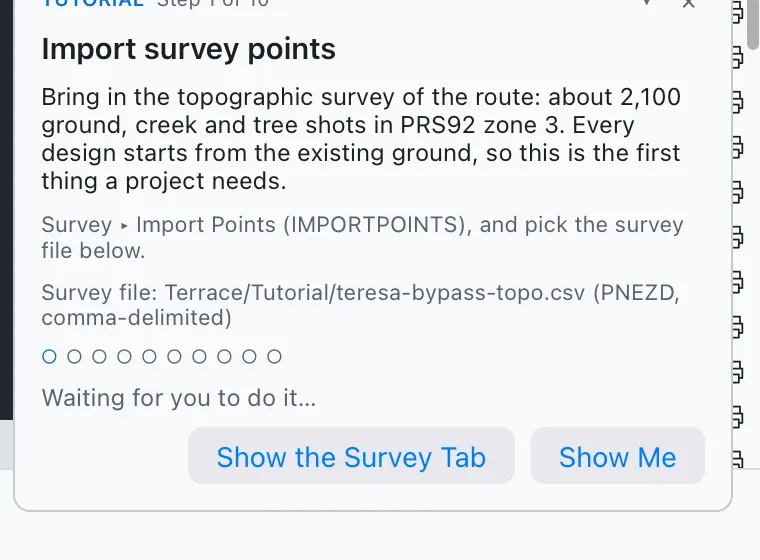
Tutorial.What the card offers:
- Show the … Tab switches the ribbon to the tab the step's button is on.
- Show Me does the step for you, as one undo step. The card says Done for you. Undo (Cmd+Z) takes it back., so you can undo and try it yourself.
- The progress dots: filled for steps done, ringed for the current one. Click a dot to jump to that step; hover it for its title.
- ‹ Back and Next › move between steps. ▾ folds the card to its title line; × closes the tutorial.
- If you switch to another drawing tab, the card says The tutorial follows another drawing. with a Go to It button.
The ten steps are: Import survey points, Build a surface, Draw the road centerline, Create the ground profile, Design the road profile, Choose a typical section, Build the corridor, Compute volumes, Drain the road, and Make plan & profile sheets. At the end, the card counts how many steps you did yourself and offers to open the sample project, which is the same road finished, with the lots along it.
Your first road in 10 minutes
This walkthrough follows the tutorial's ten steps, with the button and command for each and the chapter that explains it in full. Start the tutorial to get the survey file, then do each step yourself. Most of the buttons open a dialog with everything filled in from the project and the standard, so a step is often just a check and a click on Create. If you get stuck, Show Me on the tutorial card does the step for you. The pictures show the tutorial project made this way.
Note The Next step panel on the left follows the same order in any project, and its buttons open the same dialogs as the ribbon. See Next step.
Tip Every dialog is one undo step: ⌘Z takes back what Create made. If you prefer the command line, type the command instead (CREATESURFACE, CREATECORRIDOR…): it asks its questions there, and its first prompt offers Dialog (D, or DI when another option starts with D) to switch to the dialog. See The command line.
1. Import the survey points
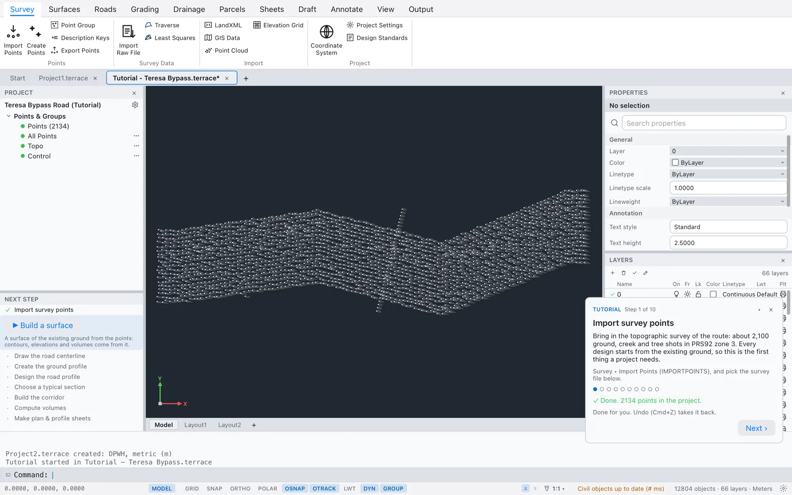
Every design starts from the existing ground. Click Survey ▸ Import Points (IMPORTPOINTS, alias POINTSIN) and pick teresa-bypass-topo.csv; the import dialog shows the first rows and the detected format (PNEZD: point number, northing, easting, elevation, description). The tutorial project gets 2,134 points, in the point groups All Points, Topo (the ground shots) and Control. More in Survey and points.
2. Build the ground surface
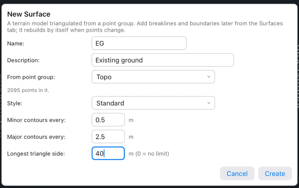
A surface (a TIN, a mesh of triangles through the points) gives elevations everywhere, and contours. Click Surfaces ▸ Create Surface (or Build a surface in Next step). The New Surface dialog opens with the name EG, the description Existing ground, the All Points group, contours every 0.5 m (major every 2.5 m) and no limit on triangle sides.
- For From point group, choose Topo, the ground shots (2,095 points), so the control points stay out.
- Type
40in Longest triangle side. Triangles longer than 40 m are left out, so the surface doesn't bridge across the empty land beyond the survey. - Click Create.
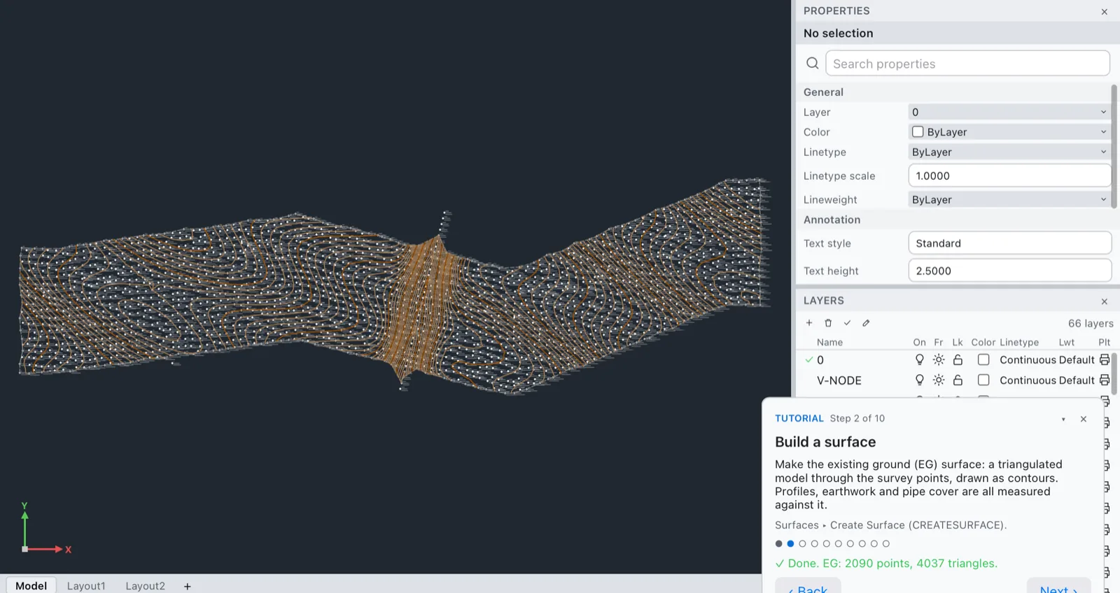
The command line says Surface EG: 2090 points, 4037 triangles, elevations 42.74 to 74.87. More in Surfaces.
3. Draw the centerline
An alignment is the road's centerline in plan. Its PIs (points of intersection) are where two straight tangents meet; each one gets a curve whose radius, spirals and superelevation follow the design speed. Click Roads ▸ Alignment. The New Alignment dialog makes a centerline from a polyline you've drawn and selected, with these defaults for a DPWH project:
- Name CL-1, Kind Road centerline, Road class National Secondary, Terrain Rolling.
- Design speed 60 km/h (From class fills it in again from the class and terrain), Max superelevation 8%.
- Curve radius at corners 115 m, the standard's minimum (113 m for 60 km/h at e = 8%) rounded up to 5 m; Minimum puts it back.
- Start station 0, Superelevation from the standard on, Erase the polyline off.
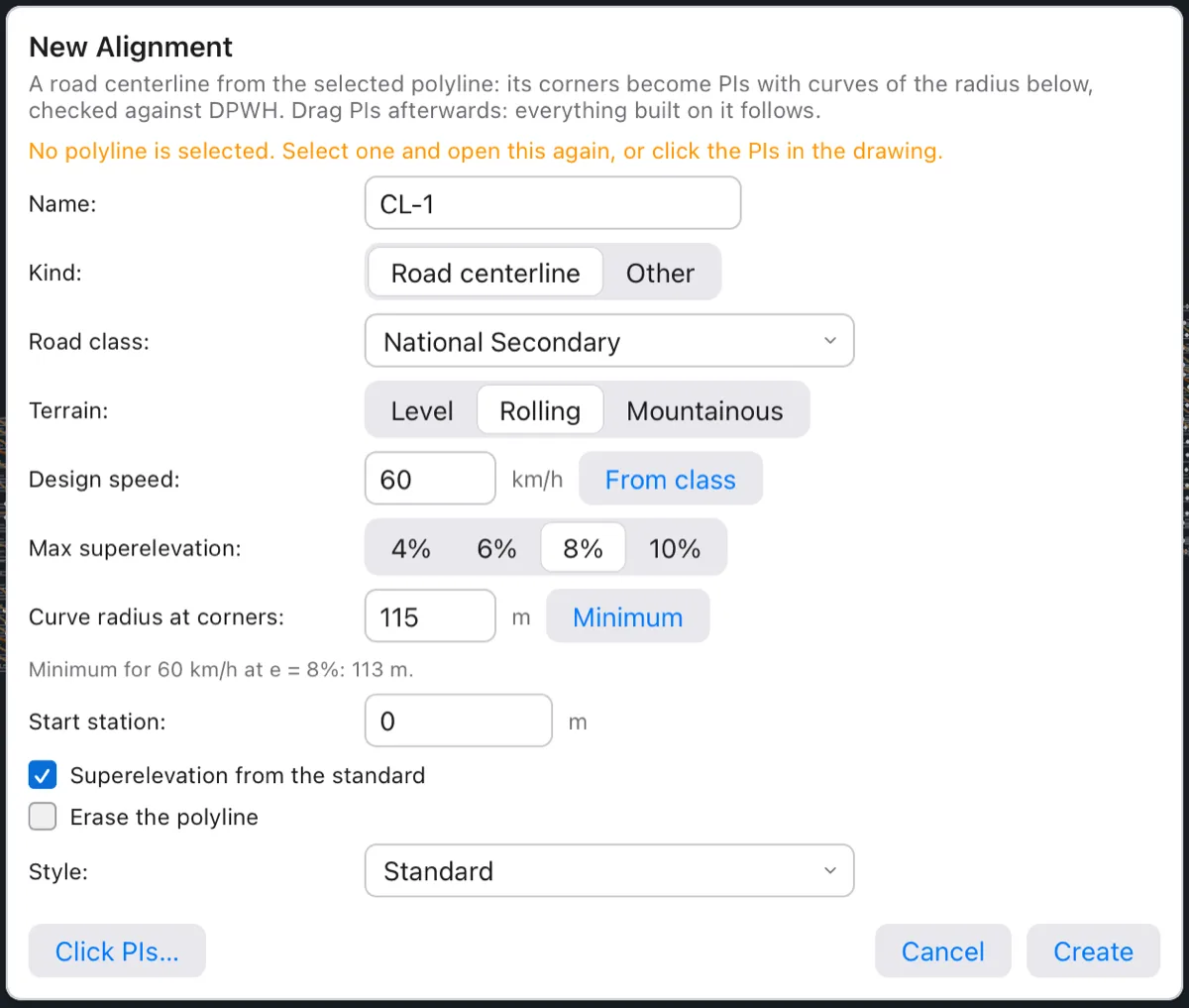
In the tutorial there's no polyline yet, so click Click PIs…: the dialog closes and CREATEALIGNMENT (CALIGN) asks you to click the PIs in the plan, one after the other, and Enter to finish. (Or draw a polyline first with PLINE, select it and open the dialog again.) The tutorial's centerline, Teresa Bypass CL, starts at station 35+200.00 and has 9 pieces: tangents, spirals and arcs. More in Alignments.
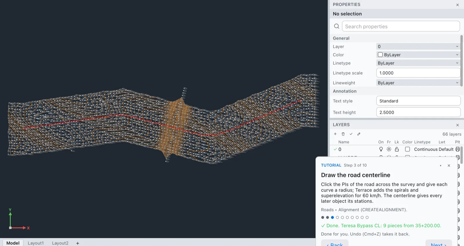
4–5. Ground profile and design profile
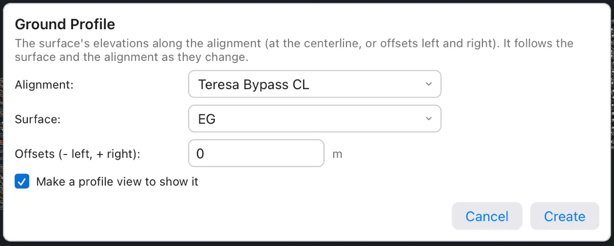
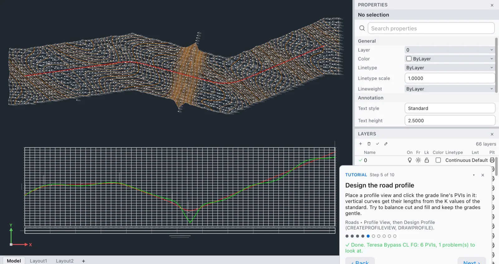
The ground profile is the EG surface cut along the centerline. Click Roads ▸ Ground Profile. The Ground Profile dialog already names the alignment (the selected one, else the one in the profile pane, else the first) and the EG surface; Offsets is 0 (type several, like -10, 0, 10, for profiles left and right), and Make a profile view to show it is on because the alignment has no view yet. Click Create: you get the profile Teresa Bypass CL - EG and the profile view PV - Teresa Bypass CL under the plan.
The design profile is the road's finished grade, a line of PVIs (points of vertical intersection) joined by vertical curves whose lengths come from the standard's K value (curve length per percent of grade change). Click Roads ▸ Design Profile. The Design Profile dialog offers:
- Name Teresa Bypass CL FG and the alignment's Design speed, 60 km/h. Use its defaults fills these in again after you pick another alignment.
- Start from Best fit to the ground: Terrace places the Number of PVIs (6 here, worked out from the road's length) to follow the ground profile, keeping every grade under the Maximum grade from the standard (6% for 60 km/h in rolling terrain). Or A straight grade between a start and an end elevation (empty = the ground's).
- Vertical curve lengths from the standard's K, on.
- Click PVIs… closes the dialog and starts
DRAWPROFILE, to click the PVIs in the profile view yourself.
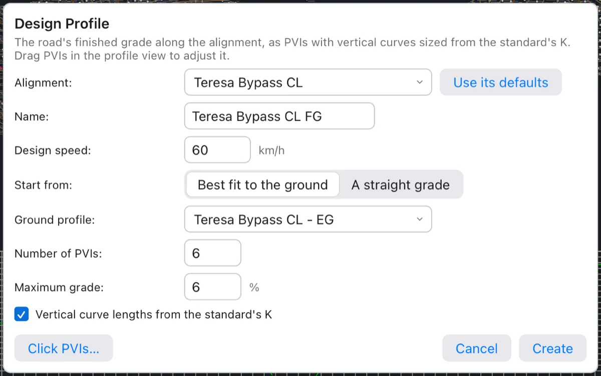
Click Create. The tutorial's best fit gives 6 PVIs and one design problem, so Next step now starts with Fix 1 problem: click it to see what's wrong and where, then drag the PVI grips in the profile view until the dot turns green. More in Profiles.
6–7. Typical section and corridor
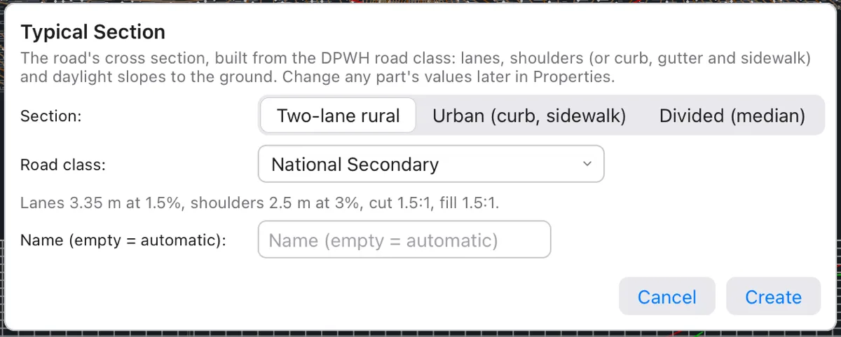
The typical section (an assembly) is the road's cross section. Click Roads ▸ Typical Section. The Typical Section dialog offers Two-lane rural, Urban (curb, sidewalk) or Divided (median), and the Road class, taken from the centerline (National Secondary). The line under it shows what the class gives: lanes 3.35 m at 1.5%, shoulders 2.5 m at 3%, cut and fill slopes 1.5:1. Leave the name empty for an automatic one and click Create: Two-lane rural (National Secondary), 6 parts.
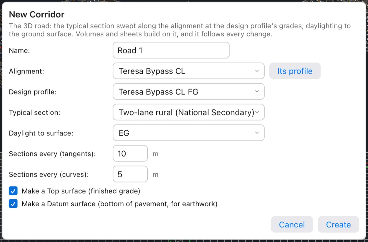
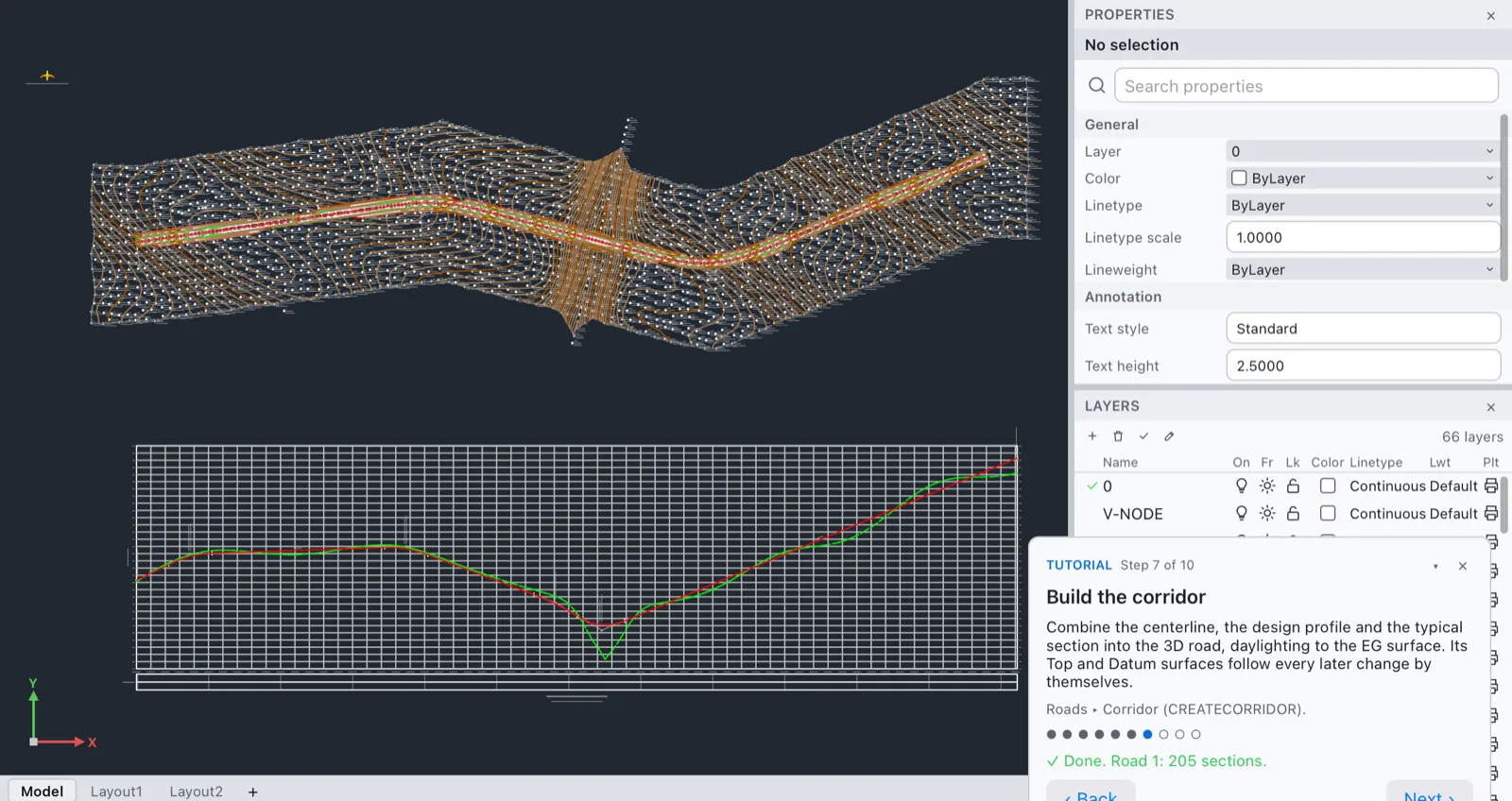
The corridor sweeps that section along the centerline at the design profile's grades, and daylights to the ground: its side slopes run out until they meet the EG surface. Click Roads ▸ Corridor. The New Corridor dialog fills in the name Road 1, the alignment, its design profile (Its profile picks it again), the typical section, Daylight to surface EG, sections every 10 m on tangents and 5 m on curves, and both Make a Top surface and Make a Datum surface (the bottom of the pavement, used for earthwork). Click Create: 205 sections, and the surfaces Road 1 Top and Road 1 Datum. More in Typical sections and corridors.
8. Volumes
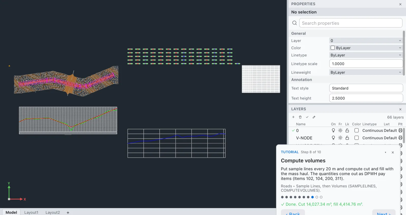
Sample lines cut cross sections across the road at a regular interval; cut and fill volumes come from them. Click Roads ▸ Sample Lines. The Sample Lines dialog fills in the name SL - Teresa Bypass CL, one every 20 m, 30 m wide on each side, also at the curve and grade points (PC, PT, PVI…), sampling the EG surface and the corridor, and drawing the section views and the mass haul diagram. Click Create: the volumes are computed at once, so the step is done without Roads ▸ Volumes (COMPUTEVOLUMES), which you use later to compute them again. More in Sections and earthwork.
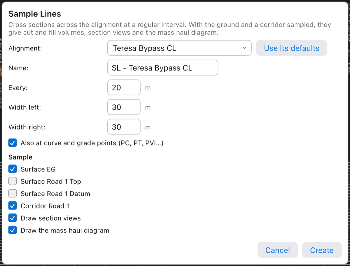
The tutorial road made this way comes to 71 sample lines, about 14,027 m³ of cut and 4,415 m³ of fill. (Your numbers follow your design profile: the sample project's hand-placed grades balance cut and fill much better.)
9. Drainage
Lay out the cross drain under the creek and catch basins at the sag, then let Terrace size the pipes from the PAGASA rainfall. Drainage ▸ Pipe Network opens the New Pipe Network dialog (storm drain or sanitary sewer, the surface the rims follow, the alignment for stations, minimum cover and slope from the standard, the rainfall station and design storm); its Lay Out by Clicking… button starts CREATENETWORK to click the structures in the plan. Then Lay Out Pipes and Design Pipes (LAYOUTPIPES, PIPEDESIGN). This step needs clicks in the right places, so Show Me is a good way through it the first time: it makes 2 networks with 8 pipes. More in Drainage and water.
10. Sheets
Cut the road into view frames and make a plan-and-profile sheet for each. Click Sheets ▸ View Frames. The Plan and Profile Sheets dialog fills in the alignment, the name Sheets - Teresa Bypass CL, Plan and profile sheets (or plan only, profile only), the profile view (Its view), an A1 (841 × 594 mm) sheet at 1:1000, 20 m of overlap at the match lines, and Make the sheet layouts now.
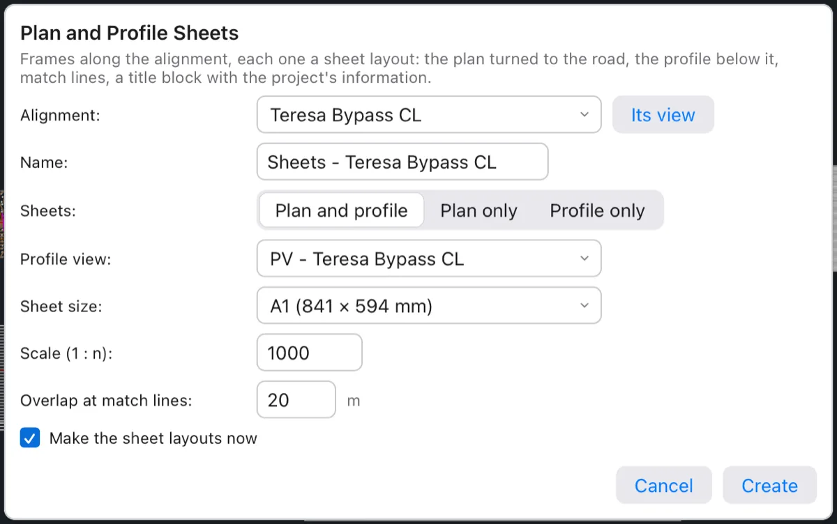
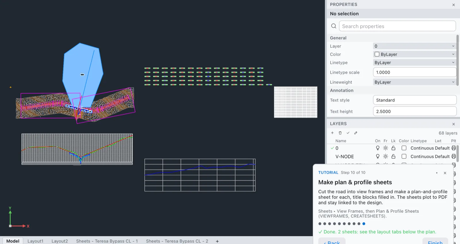
Click Create: 2 view frames and 2 sheet layouts, as the tabs Sheets - Teresa Bypass CL - 1 and - 2 under the plan. More in Sheets and plotting and Reports.
Note The tutorial card may keep saying Waiting for you to do it… after this dialog, although the sheets are made and Next step ticks the step. Click Sheets ▸ Plan & Profile Sheets and press Enter (it says 2 sheets made (0 new layouts).): the card then says Done.
Now change something
This is where Terrace pays off. Everything you just made is linked: move a PI of the centerline and the profiles, corridor, volumes and sheets follow, usually in a fraction of a second. Read Selecting and editing next, then The window for every panel, and Projects and files before your first real job.