
Survey and points
This chapter covers the survey side of Terrace: COGO points, point groups, description keys, point files, total-station raw files, traverse and least squares adjustment, and the project's coordinate system. When you finish it you'll be able to bring a field survey into a project, check and adjust it, and sort its points so the surfaces and designs that follow are built from the right shots.
The Survey tab
Everything in this chapter starts from the Survey ribbon tab, the first tab of the window. Its groups follow the order of the work:

| Group | Button | Command (aliases) | What it does |
|---|---|---|---|
| Points | Import Points | IMPORTPOINTS (POINTSIN) | Reads a point file (PNEZD, PENZD …) with a preview |
| Create Points | CREATEPOINTS (CPOINTS, COGOPOINT) | Points by clicking or by typing northing, easting, elevation | |
| Point Group | POINTGROUP (PGROUP) | Opens the New Point Group dialog: a named set of points by number, code or elevation | |
| Description Keys | DESCKEYS (DKEYS) | Field codes → descriptions and layers | |
| Export Points | EXPORTPOINTS (POINTSOUT) | Writes every point to a point file | |
| Survey Data | Import Raw File | IMPORTRAW (RAWIN) | Total-station observations (RW5, SDR, GSI, CSV) reduced to points |
| Traverse | TRAVERSE (TRAV, ADJUSTTRAVERSE) | Compass, transit, Crandall or least squares traverse adjustment | |
| Least Squares | LEASTSQUARES (LSQ, NETWORKADJUST) | Adjusts the whole network of observations | |
| Import | LandXML, GIS data, point clouds and elevation grids: see Importing and exporting. | ||
| Project | Coordinate System | COORDINATESYSTEM (CRS, EPSG) | PRS92 zones, Luzon 1911, UTM, WGS 84; the combined factor |
Project Settings and Design Standards in the same group open their dialogs; they are covered in Projects and files and Standards and styles. All the commands are also listed in the command reference.
Note If no project is open when you click a Survey button, Terrace starts a new project first (DPWH, metric) and runs the command in it.
COGO points
A COGO point (coordinate geometry point) is one surveyed position: a point number, a northing, an easting, an elevation (or none) and a description. Every surface, profile and stakeout in Terrace starts from them. Northing is the drawing's Y and easting its X.
Each point keeps two descriptions. The raw description is the code as the field crew typed it (TREE 0.3 MANGO). The full description is what the description keys make of it (Tree 0.3 m MANGO). Labels show the full description; point groups can match either.
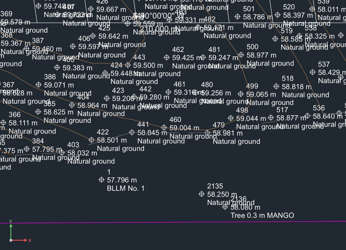
In the sample project the 2,134 points are numbered from 1: control first (BLLM No. 1, BM-1, BM-2), then the ground shots (NGL), the creek bed (CRK) and the trees. Point markers go on layer V-NODE and their labels on V-NODE-TEXT, unless a description key names another layer.
Creating points by clicking
Use this to add a few points where you can see them: a spot you need on the plan, a missing shot, a point read off a sketch.
- Click Survey ▸ Create Points (or type
CREATEPOINTS, aliasCPOINTS). The command line says the next free point number. - At Specify point location or [Typed/Number], click the location.
- At Elevation [None/Surface], press Enter to take the default. When there's a ground surface under the point, the default is its elevation there; otherwise it's the last elevation you typed. Type a number to give another, N for no elevation, or S for the surface's.
- At Description, type the code (for example
NGL) or press Enter to repeat the last one. - Click the next location, or press Enter to finish.
Each point is reported on the command line as it is made. All the points of one run are one undo step, and surfaces built from them are brought up to date once when the command ends, so even a long run stays quick.
To start numbering somewhere else, type N (Number) at the location prompt and give the next point number. Numbers already used are skipped.
Typing coordinates
Use this to key in points from a field book or a list of control coordinates.
- Start
CREATEPOINTSand type T (Typed) at the first prompt. - At Enter northing,easting,elevation[,description], type a line the way surveyors write it: northing first. For example
1610195.500,522648.200,58.080,TREE 0.3 MANGO. Spaces between the numbers work too; the elevation and description can be left off. - Press Enter and type the next line. Press Enter on an empty line to finish.

NGL into “Natural ground”.A line without a description takes the last one you used.
Tip A new NGL point joins the Topo group, so the EG surface built from that group takes it in as soon as the command ends. You'll see the contours move around it.
Moving, copying and deleting points
Points are edited like any other civil object (see Selecting and editing):
- Move: click a point and drag its grip, or use
MOVE. Its northing and easting change; its number, elevation and description stay. - Copy:
COPYmakes new points with the next free numbers. - Delete:
ERASE. Terrace says what depended on them before it removes them. - Locked points (some imports lock control points) refuse to move.
Selecting points shows a summary in the Properties panel: how many points the project has, how many have an elevation, the elevation range, the number of point groups and description keys. A point's own elevation and description can't be typed over in the panel; to change them, import the point again with Replace the old (see Importing a point file).
Point groups
A point group is a named set of points chosen by rules: by number, by code, by elevation. Surfaces are built from groups, so groups decide which shots go into the ground model. A group keeps itself up to date: a new NGL point joins a group that takes NGL* without you doing anything.
The sample project has three: All Points, Topo (codes NGL*,CRK*: the ground and creek shots the EG surface is built from) and Control (BLLM*,BM*).
Making a group
Make a group when you want a surface, a report or an export to use only some of the points: the ground shots, the trees, one day's work.
- Click Survey ▸ Point Group. The New Point Group dialog opens with a free name filled in (Group 1 in a project that has none).
- Type a Name and, if you like, a Description.
- Say which points belong to it. Tick Every point in the project for all of them (the other rules then hide), or fill in one or more of:
- Point numbers: ranges like
1-50, 75; - Codes: field codes like
GND*, TOE, EP*(*matches anything,?one character; capitals don't matter); - Elevations: ranges like
90-120, or a single elevation.
- Point numbers: ranges like
- Put numbers to keep out in Leave out numbers (for example a bad shot).
- Watch the line under the fields: It holds … of the project's … points now counts the members as you type. Click Create.
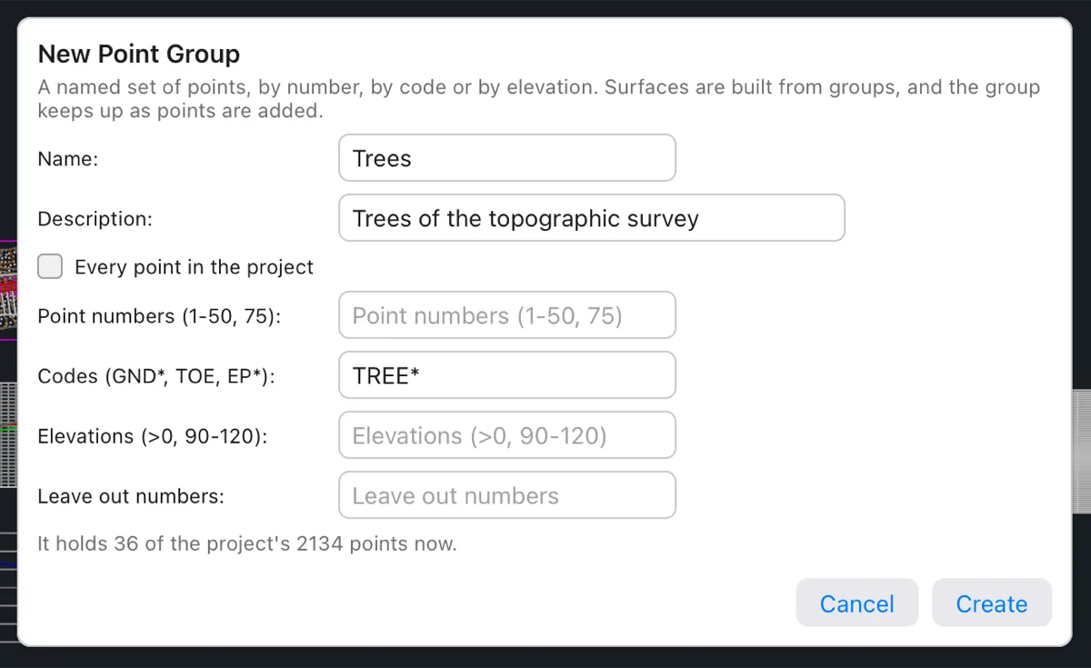
The group appears in the Project browser under Points & Groups, and the command line says how many points it holds. It's one undo step. A name already used is refused, and so is an empty one.
Note The Elevations field's hint shows >0, but Terrace reads only ranges and single values there: >0 matches nothing. Type a range such as 0-9999 instead.
Or type POINTGROUP (alias PGROUP) to make the group on the command line:
- At Point group name [Dialog], type a name or press Enter for the suggested one. Type D (Dialog) here to open the New Point Group dialog instead.
- At Include points by [All/Numbers/Descriptions/Elevations], choose one:
- A (or Enter): every point in the project;
- N: point numbers as ranges, like
1-100,205; - D: descriptions, like
EP*,CL*; - E: an elevation range, like
100-150.
- Type the numbers, codes or range. Terrace says how many points the group holds.

Changing a group's rules
Click a group in the Project browser: its rules show in Properties, and you can change any of them. Every change is one undo step, and every surface built from the group rebuilds by itself.
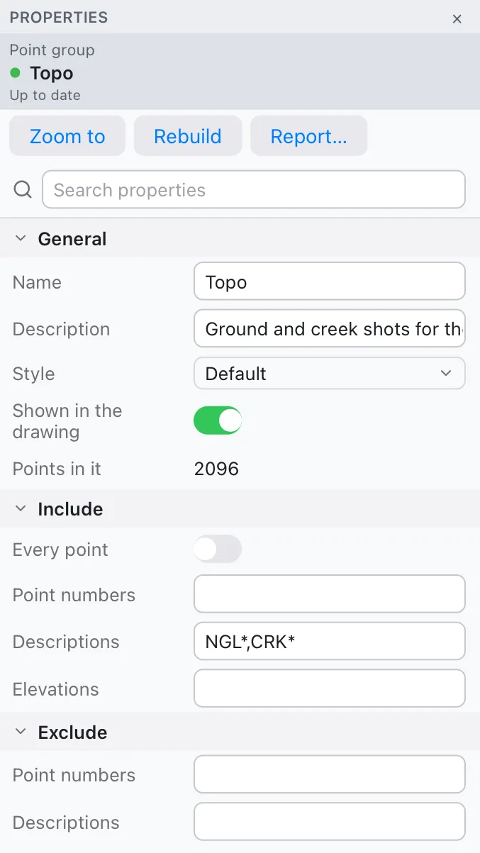
| Row | What it does |
|---|---|
| Name, Description | The group's name (shown everywhere) and a note. |
| Style | How its points look: Standard (circle-cross with number, elevation and description), Marker Only, Number and Elevation. |
| Shown in the drawing | Turn off to hide the group's points (its surfaces still use them). |
| Points in it | How many points match now. |
| Include ▸ Every point | All points of the project. |
| Include ▸ Point numbers | Ranges like 1-100,205. |
| Include ▸ Descriptions | Codes like EP*,CL* (* and ? match anything). |
| Include ▸ Elevations | A range like 100-150. Points without an elevation never match it. |
| Exclude ▸ Point numbers, Descriptions | Points to leave out even when an include rule takes them. |
A point belongs to the group when it matches any include rule and no exclude rule. A group with no include rule at all is empty.
The Report… button opens the point group report: every member with its northing, easting, elevation and descriptions (see Survey reports).
Tip To keep a bad shot out of the ground model, add its number to Exclude ▸ Point numbers of the group the surface is built from. The surface rebuilds without it, and the point stays in the project.
Description keys
Field crews type short codes: NGL, CRK, TREE 0.3 MANGO. Description keys turn each code into a readable description and put the point on the right layer, so the plan reads well and you can turn whole classes of points on and off by layer.
- Click Survey ▸ Description Keys (or type
DESCKEYS, aliasDKEYS). - Edit the table: double-click a cell to change it. Add key adds a row; select rows and click Delete keys to remove them.
- Leave Apply to the points already in the project ticked to redo the descriptions of the points you have, then click OK.
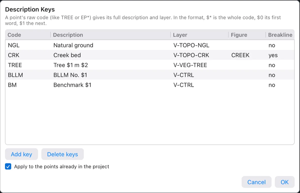
| Column | What it means |
|---|---|
| Code | Matched against the first word of a point's raw description. * and ? are wildcards (EP* takes EP1, EP2 …). The first key that matches wins. |
| Description | The full description to make. $* is the whole raw description, $0 its first word, $1 the second word, $2 the third, and so on. With Tree $1 m $2, the raw code TREE 0.3 MANGO reads “Tree 0.3 m MANGO”. |
| Layer | The layer for the point's marker and label (empty: the point style's layers, V-NODE and V-NODE-TEXT). |
| Figure, Breakline | Stored with the key, for survey linework. Terrace doesn't draw figures from coded points yet, so these two columns have no effect for now. |
A point whose code matches no key keeps its raw description as its full description. Keys apply to every point you add from then on: typed, clicked or imported.
Importing a point file
Most surveys reach the office as a text file of points: one point per line, with number, northing, easting, elevation and description in some order. The Import Points dialog reads them with a preview, so you can see the columns are right before anything is added.
- Click Survey ▸ Import Points (or type
IMPORTPOINTS, aliasPOINTSIN) and choose the file (.csv,.txt,.pnt,.nez,.xyz). You can also drop the file on the window (see Drag and drop). - Read the line under the title: how many lines the file has, and the column order and separator Terrace found.
- Check the preview table: its columns are Point, Northing, Easting, Elevation and Description, read the way the settings say. If the northings sit under Easting, change Columns; the preview follows at once.
- Choose what to do with numbers already in the project, and whether to make a point group and a surface.
- Click Import.
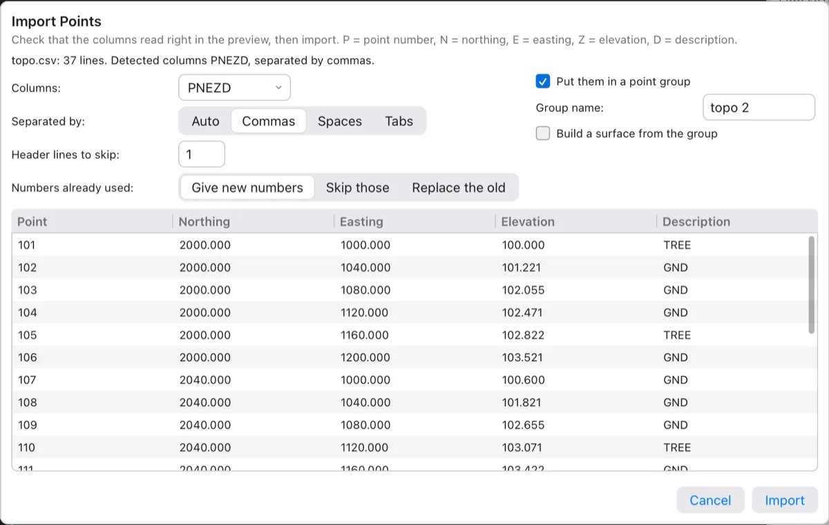
| Field | Choices and default |
|---|---|
| Columns | The column order: PNEZD, PENZD, PNEZ, PENZ, NEZ, ENZ, NEZD, ENZD (P = point number, N = northing, E = easting, Z = elevation, D = description). Detected from the file's first lines. |
| Separated by | Auto, Commas, Spaces or Tabs. Detected. |
| Header lines to skip | Lines at the top that aren't points (column titles). Detected. Lines starting with # are always skipped. |
| Numbers already used | Give new numbers (default: the clashing points get the next free numbers), Skip those, or Replace the old (the project's point takes the file's coordinates, elevation and description). |
| Put them in a point group | On by default; the Group name is the file's name. The group lists the imported numbers. |
| Build a surface from the group | On by default when the project has no surface yet; the Surface name is EG. One click from field file to ground model. |
A file without point numbers (NEZ, ENZ …) gets numbers from the next free one; the preview shows them as “(next)”. The import is one undo step, and the command line says how many points came in, how many were replaced or skipped, and the group and surface made.
Watch out The command-line form -IMPORTPOINTS asks for the file and then Column order [Auto/PNEZD/PENZD/PNEZ/PENZ/NEZ/ENZ]. Pick an order there; the Auto choice currently fails with “the column order "A" has "A"”. The dialog's detection works.
Total-station raw files
A raw file holds what the total station measured, not coordinates: for each setup (the instrument over a known point, sighting a backsight), the horizontal angle, zenith angle and slope distance to every shot, with instrument and target heights. Terrace reads the observations and reduces them: it computes each shot's coordinates from the station and backsight. Keeping the observations lets you adjust the traverse and the network afterwards.
| Format | Extension | Instruments |
|---|---|---|
| Carlson RW5 | .rw5 | Carlson SurvCE / TDS data collectors |
| Sokkia SDR | .sdr | Sokkia SDR33 |
| Leica GSI | .gsi | Leica GSI-8 and GSI-16 |
| Raw CSV | .csv, .txt | Any instrument, as a table: station,bs,ih,point,hz,zen,sd,ht,desc (angles as 90-00-00) |
- Put the control in first: the station and backsight points need coordinates. Import or type them (they may also be in the raw file itself: RW5
SPrecords and similar are read as known points). - Click Survey ▸ Import Raw File (or type
IMPORTRAW, aliasRAWIN) and choose the file. - Check the File format (picked from the extension; choose another and click Read again if it's wrong) and the summary line: setups, observations and points with known coordinates.
- Look over the observations in the table: Station, Backsight, Point, Horizontal, Zenith, Slope dist., Target ht., Description.
- Choose Point numbers already used: Keep the project's (default) or Replace with the file's, and whether to Put the points in a point group (named after the file). Click Import.
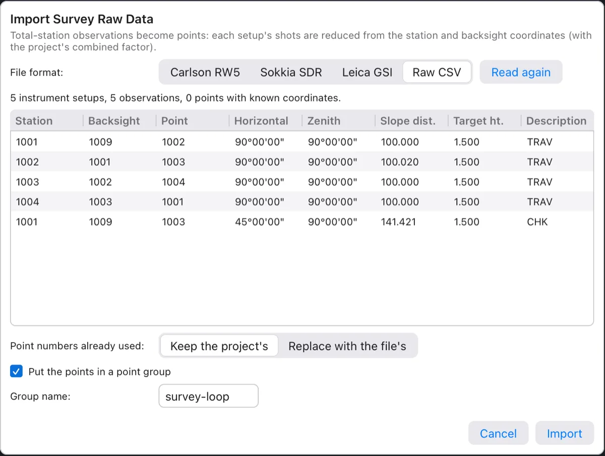
What reduction does for you:
- Setups are reduced in file order; a setup's station must be known by then (from control, or from an earlier setup's shot).
- Horizontal distances are multiplied by the project's combined factor, so ground distances become grid distances.
- Elevations come by trigonometric levelling, with instrument and target heights.
- Shots to a backsight, to control points, to locked points, and repeated shots are checks: they move nothing, and a note says so when one misses by more than 0.01 m.
- Point names that aren't numbers (like
CP1) get numbers after the highest one in the file, and a note tells you which.
The setups and observations stay in the project for TRAVERSE and LEASTSQUARES. Importing again adds the new setups to them.
Traverse adjustment
A traverse is a chain of setups, each one sighting back to the last and ahead to the next. Measurement errors add up around it, so a closed loop never quite closes. The misclosure is how far it misses; the precision is the length of the traverse divided by that miss (1:20,000 means 1 cm in 200 m). Adjusting spreads the miss back over the stations so the traverse closes.
- Import the raw file (above).
TRAVERSEneeds observations; without them it says “import a raw file first”. - Click Survey ▸ Traverse (or type
TRAVERSE, aliasTRAV). - At Stations in order, press Enter to take the suggestion (the setups' stations in order, the first repeated to close a loop:
1001,1002,1003,1004,1001) or type your own. At least three stations. - At Backsight point at the first station (0 = none), press Enter for the first setup's backsight.
- At Adjust by [Compass/Transit/CRandall/Least squares], choose the rule (Enter for the last one used; Compass the first time).

| Rule | Key | How it corrects | When to use it |
|---|---|---|---|
| Compass (Bowditch) | C | Each course's latitude and departure in proportion to its length. | The usual choice when angles and distances are about equally good. |
| Transit | T | Latitudes in proportion to the latitudes, departures to the departures. | Angles measured better than distances. |
| Crandall | CR | Holds the balanced directions and corrects only the distances (weighted least squares). | Very good angles (a modern total station), taped or poorer distances. |
| Least squares | L | The traverse's observations adjusted together, holding its known start, backsight and closing points. | The most rigorous answer; extra observations count. |
The angular misclosure is first balanced equally over the angles; elevation misclosure is spread by distance. The adjusted points move, as one undo step, and the command line lists every course (from, to, direction, distance, the latitude and departure corrections, adjusted northing and easting), then the misclosure and the precision:

The traverse is kept by name (Traverse 1, Traverse 2 …). Run TRAVERSE again to re-adjust it with another rule: it lists the traverses and asks Traverse name or [New]; Enter takes the first one, N defines a new one.
The Traverse adjustment report shows the adjusted coordinates with the method, misclosures and the course table, ready to save as CSV or PDF:
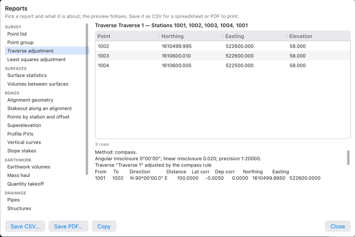
REPORT ▸ Traverse adjustment). It reports the first traverse of the project.Least squares network adjustment
When a survey has more measurements than it strictly needs — shots to the same point from two setups, ties between traverses, check shots — least squares uses all of them at once. It finds the coordinates that make the sum of the weighted squared residuals smallest, and tells you how good each point is.
- Import the raw files of the network.
- Click Survey ▸ Least Squares (or type
LEASTSQUARES, aliasLSQ). - At Control points to hold fixed (numbers or ranges), press Enter for the default (the first setup's station and backsight:
1001,1009) or type your control points. Hold at least one point, and two to fix the orientation when there's no backsight azimuth.

The command line shows the report (up to 60 lines) and moves the adjusted points, as one undo step. What it says:
| Term | Meaning |
|---|---|
| Residuals | For each observation, adjusted minus measured. Large ones point to a blunder. |
| Standard errors (σ N, σ E) | How uncertain each adjusted point is, in project units. |
| Error ellipse (a, b, orientation) | The point's uncertainty as an ellipse: semi-major axis, semi-minor axis and the direction of the long one. |
| Reference variance, degrees of freedom | How well the residuals agree with the expected instrument accuracy (near 1 is right), and the number of redundant measurements. |
| Chi-square test | At 95 %: passed when the reference variance is within what chance explains; FAILED means a blunder or the wrong instrument accuracy. |
| Notes | Check shots that miss, as during reduction. |
The instrument accuracy assumed by default: distances 3 mm + 2 ppm, angles 5″, centering and target 2 mm.
Watch out The Least squares adjustment entry of the Reports dialog has no field for the fixed points yet, so it always says “hold at least one point fixed”. Use the LEASTSQUARES command and read its output on the command line.
Coordinate systems
Philippine surveys are tied to PRS92, the Philippine Reference System of 1992: a Transverse Mercator grid in five zones, 2° wide. Older plans use Luzon 1911 on the same zones. Setting the project's system lets Terrace exchange data with GIS files and Google Earth, and work out the combined factor. New projects start with none (plain local coordinates); the sample project is in PRS92 zone 3 (EPSG:3123).
- Click Survey ▸ Coordinate System (or type
COORDINATESYSTEM, aliasCRSorEPSG). The command line shows the current system. - At EPSG code or [List/None], type the code (the default is the current one, or 3123), L to list every system Terrace knows, or N to go back to local coordinates (factor 1).
- At Combined factor (grid × elevation) or [Compute], type the factor, press Enter to keep the current one, or C to compute it.
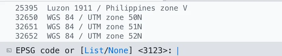
| EPSG | System |
|---|---|
| 3121 – 3125 | PRS92 / Philippines zones 1 to 5 (central meridians 117° to 125° E, scale 0.99995) |
| 25391 – 25395 | Luzon 1911 / Philippines zones I to V |
| 32650 – 32652 | WGS 84 / UTM zones 50N to 52N (other UTM zones by code: 32601–32660 north, 32701–32760 south) |
| 4326, 4683, 4253 | WGS 84, PRS92 and Luzon 1911 longitude/latitude |
The combined factor
A distance measured on the ground isn't the same length on the grid. The grid scale factor (from the projection, about 0.99995 near a PRS92 central meridian) and the elevation factor (the ground is above the ellipsoid) together make the combined factor: grid distance = ground distance × combined factor. Terrace applies it when reducing raw observations.
C (Compute) works it out at the center of the project's points and their mean elevation:

A factor must be between 0.9 and 1.1 (real ones are 0.9996 to 1.0004). For a longitude/latitude system the factor is 1. The coordinate system and factor are also in Project Settings (see Projects and files). The change is one undo step.
Note Changing the system doesn't move the points: it says what system their coordinates are in. To bring in data from another system, import it (GIS files are transformed into the project's system: see Coordinate transforms).
Exporting points
Send points to a data collector for stakeout, or to another program.
- Click Survey ▸ Export Points (or type
EXPORTPOINTS, aliasPOINTSOUT). - At Point file to write, type the file name (for example
survey-points.csv). - At Column order [PNEZD/PENZD/PNEZ/PENZ/NEZ/ENZ], pick the order or press Enter for PNEZD.

The file is comma-separated with four decimals, and holds every point of the project with its full description. To send only some points, use the Point list report's Save CSV… (below), or export LandXML or GIS data (see Importing and exporting).
Survey reports
Type REPORT (or click Report… on a point group in Properties) and pick one under Survey. Each shows a live preview and saves as CSV or PDF; see Reports for the dialog.
| Report | What it lists |
|---|---|
| Point list | Point, northing, easting, elevation, raw and full description; for all points or one group, and optionally Only points (e.g. 1-20, 35). |
| Point group | The members of a group with the group's description. |
| Traverse adjustment | The adjusted points of the first traverse, method, misclosures, precision and course table. |
| Least squares adjustment | Adjusted points with σ N, σ E and error ellipses (see the warning in Least squares). |