Pro: junctions, turning paths and optimisation
This chapter covers the Pro Design tab of Terrace Pro: intersections and roundabouts, vehicle turning paths, profile optimisation with alignment alternatives, and the 3D view with its drive-through. When you finish it you'll be able to design a junction for a design vehicle, prove a truck can make the turn, let Terrace search for a cheaper grade line or route, and look at the whole road in 3D.
The Pro Design tab
Everything in this chapter is on the Pro Design ribbon tab. It has a Terrace Pro button (the license window) and four groups: Junctions, Turning Paths, Optimize and 3D. In Terrace Free the buttons show a lock and open the Terrace Pro window instead; see Terrace Pro.

| Button | Command (aliases) | What it does |
|---|---|---|
| Junction Designer | JUNCTION (JDESIGN) | Opens the guided Junction Designer window |
| Intersection | INTERSECTION (INTX) | Designs the intersection of two roads at the command line |
| Roundabout | ROUNDABOUT (RBT) | Designs a roundabout where roads meet, checked against the FHWA guide |
| Junction Report | JUNCTIONREPORT (JREPORT) | Lists a junction's design and checks |
| — | JUNCTIONEDIT (JEDIT), JUNCTIONDELETE (JDELETE) | Opens a junction in the designer; deletes a junction and the alignments it made |
| Swept Path | SWEPTPATH (SWEPT, TURNPATH, VEHICLEPATH) | Drives a design vehicle along an alignment, polyline, line or arc |
| Minimum Turn | SWEPTTEMPLATE (TURNTEMPLATE, MINTURN) | Draws a vehicle's minimum turning path at a point |
| Swept Path Report | SWEPTREPORT (SWEPTREP) | The widths, off-tracking and steering of a swept path |
| Paths & Vehicles | SWEPTPATHS (TURNINGPATHS, VEHICLES) | Opens the Turning Paths window; SWEPTDELETE (SWEPTDEL) removes a path |
| Optimize | OPTIMIZE (OPTIMISE, OPTWIN) | Opens the Optimize window |
| Optimize Profile | OPTIMIZEPROFILE (OPTIMISEPROFILE, OPTPROF) | Makes the least-cost design profile it can find as a new profile |
| Alternatives | ALIGNALTERNATIVES (ALTALIGN, ALTS) | Generates and ranks variants of an alignment |
| Adopt Alternative | ADOPTALTERNATIVE (ADOPTALT) | Makes a variant a real alignment with its profiles |
| 3D View | VIEW3D (3D, V3D, 3DVIEW) | Opens the 3D view |
| Drive-Through | DRIVE (DRIVETHROUGH) | Drives along an alignment at a driver's eye height |
| Exaggeration | EXAGGERATION3D (VEXAG, EXAG3D) | Sets the 3D view's vertical exaggeration |
All of them are also in the command reference. The examples below use the sample project (Help ▸ Open the Sample Project) with two side roads added: CL-1 crossing the Teresa Bypass near Km 35+421 and CL-2 crossing it further east. You can draw such a road with Roads ▸ Alignment (see Alignments).
Intersections
Where two roads cross, the corners need curb returns: curves at the edge of the travelled way that let the largest vehicle using the junction turn without running over the curb. That vehicle is the design vehicle. Terrace reads each corner's turn angle, looks up the curb return radius that vehicle needs in the AASHTO turn table, works out how much the lane must widen through the turn, and draws it all.
With the INTERSECTION command
- Click Pro Design ▸ Intersection (or type
INTERSECTION). If an alignment is already selected, it becomes the primary road. - Select the primary road, the one that goes straight through (here Teresa Bypass CL), then the crossing road (CL-1). You can click them or type a name. If they don't cross, Terrace says so and stops.
- At Design vehicle, press Enter for the default WB-15 or click another (P, SU-9, BUS-12, CITY-BUS, WB-12, WB-15, WB-19, WB-20). Terrace remembers your choice for next time and lists each corner it will make.
- At Curb return radius, press Enter for Auto (each corner from the turn table) or type one radius for every corner.

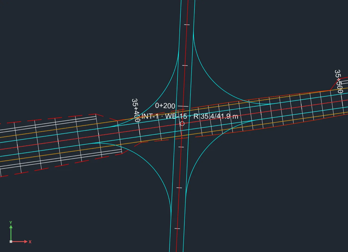
For the sample, the log explains every corner in plain words, for example: "Corner 1: 79° between the roads, a 101° turn. A WB-19 turning 101° needs a 35.4 m curve with the edge offset 1.0 m and a 19:1 taper (AASHTO Table 9-14) (the turn table has no rows for WB-15; using WB-19's). The turning WB-15 sweeps 5.46 m at 15 km/h (AASHTO 3.3.10): widen the 3.35 m lane by 2.11 m through the return." The roads cross at 79.2°, so two corners get 35.4 m returns and two get 41.9 m.
What it makes
- When both roads are baselines of one corridor, the corridor is split: edge alignments, curb returns with their own profiles, and the crossing road cut back to the curb returns.
- When they aren't (the usual case, as in the sample, where CL-1 has no corridor), Terrace makes edge-of-travelled-way alignments one lane width from each centerline (the lane width comes from the road's class, 3.35 m for a DPWH National Secondary road) and curb return alignments between them. The log says which it did.
The junction is named INT-1, INT-2…, drawn on the C-ROAD-JUNC layers, and saved with the project. It follows its roads: move a PI of either road and the returns are made again. ⌘Z takes the whole intersection back in one step.
Note Terrace has no command yet that adds a second baseline to a corridor, so on your own projects you'll normally get the edge-offset version; the corridor isn't trimmed around the junction.
Roundabouts
A roundabout replaces the crossing with a one-way circle. Its size and the shape of its entries decide how fast drivers go in, which is what makes it safe. Terrace sizes one from the FHWA Roundabouts: An Informational Guide categories and checks the result against the guide's values.
With the ROUNDABOUT command
- Click Pro Design ▸ Roundabout (or type
ROUNDABOUT). - Select the roads that meet there, one at a time (click them or type their names), and press Enter when done. Here: Teresa Bypass CL and CL-2.
- At Center of the roundabout, press Enter for Crossing (where the first two roads cross) or click the center.
- At Category, pick Mini, Compact, Urban1 (the default), Urban2, Rural1 or Rural2. Terrace prints the category's range, e.g. "Urban single-lane: inscribed diameter 30.00 m to 40.00 m, entry speed up to 35 km/h, for the WB-15 (FHWA Exhibits 1-7, 6-19)."
- At Inscribed circle diameter, press Enter for the middle of the range (35 m for Urban1) or type your own.
Each place a road crosses the circle becomes a leg: a road through the center gives two legs, a road ending there gives one. For the sample the log reads "RB-1: Urban single-lane roundabout, 35.00 m inscribed diameter, 4 legs, for the WB-15" and "RB-1: 37 of 37 FHWA checks met".
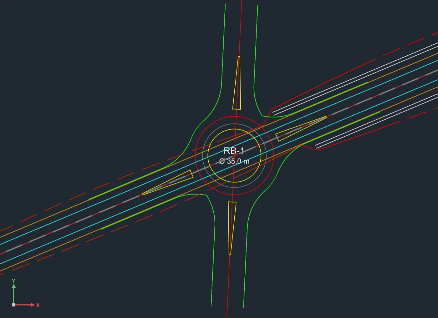
A roundabout is made of alignments (the circulatory roadway's centerline and every curb) and linework: the outer curb, entry and exit curbs (arcs tangent to the lane edge and the circle), the splitter islands, the central island and the truck apron, on the C-ROAD-JUNC-CURB, -ISLD, -APRN and -TEXT layers. The defaults per category:
| Category | Diameter range | Entry speed up to | Lanes | Design vehicle |
|---|---|---|---|---|
| Mini-roundabout | 13–25 m | 25 km/h | 1 | SU-9 (no truck apron) |
| Urban compact | 25–30 m | 25 km/h | 1 | BUS-12 |
| Urban single-lane | 30–40 m | 35 km/h | 1 | WB-15 |
| Urban double-lane | 45–55 m | 40 km/h | 2 | WB-15 |
| Rural single-lane | 35–40 m | 40 km/h | 1 | WB-20 |
| Rural double-lane | 55–60 m | 50 km/h | 2 | WB-20 |
Note A roundabout draws its own curbs over the roads but doesn't cut a corridor that runs through it: rebuild or trim the corridor regions yourself.
The Junction Designer
The Junction Designer does the same work as the two commands, in a window that shows each choice with the reason for it and a preview before anything is made. Click Pro Design ▸ Junction Designer (JUNCTION). Four buttons across the top switch pages: Junctions, New Intersection, New Roundabout and Design Vehicles. Close is at the bottom right.
The list of junctions
The Junctions page lists the project's intersections and roundabouts with a one-line summary, and for each an Edit, Report and Delete button. Report shows the full report under the list, the same text JUNCTIONREPORT writes to the log: the roads and crossing angle, each corner, what was made, and the sources.
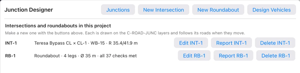
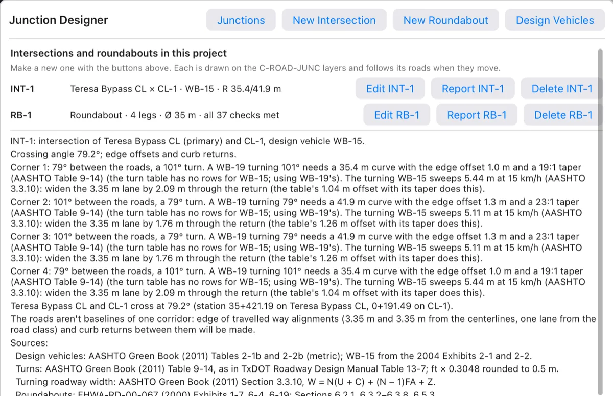
JUNCTIONEDIT opens a junction straight in the designer, and JUNCTIONDELETE deletes one with the alignments it made. Both, and JUNCTIONREPORT, ask you to name the junction (Enter takes it when there's only one) or click near its crossing or circle.
New Intersection
- The roads: pick the Primary road and the Crossing road. The project needs two road centerlines that cross.
- Design vehicle: pick it from the list; the line under it gives its length, width and minimum turning radius.
- Curb return radius: Auto, or a number used at every corner.
- What will be made: read the preview (crossing, what kind of junction, each corner), then click Make Intersection.
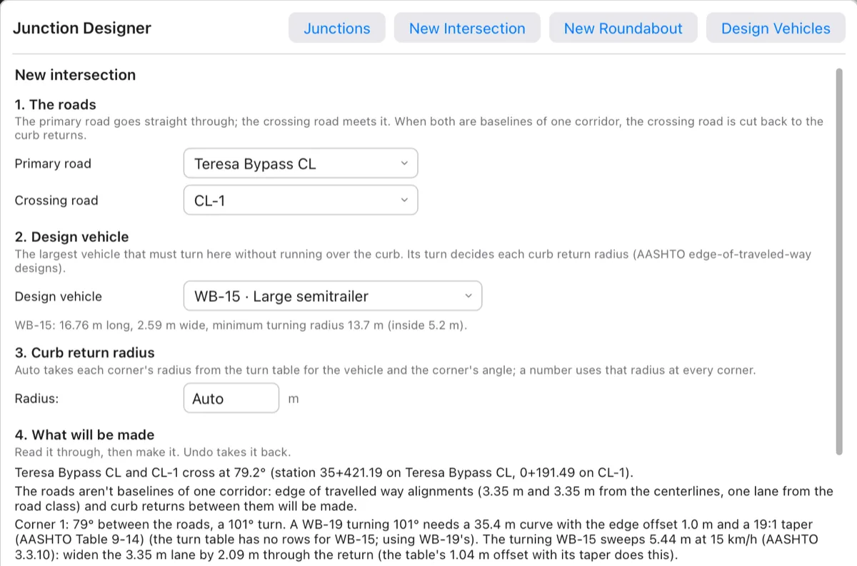
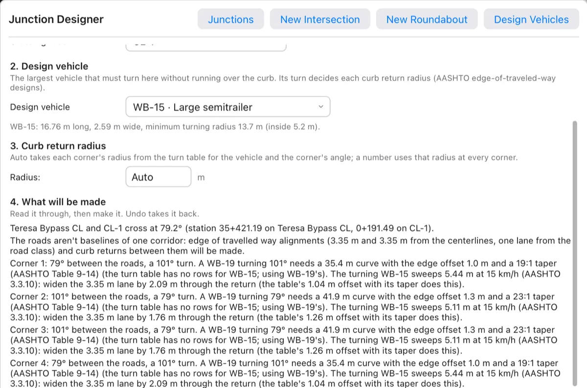
When you edit an intersection the button reads Apply Changes; it's one undo step either way.
New Roundabout
The roundabout page has the same steps as the command plus everything the command fills in for you:
| Step | Field | Default (Urban single-lane) | What it does |
|---|---|---|---|
| 1. The roads that meet | A ☐/☑ button per road | — | Tick the roads that make legs |
| 2. Center | Center X (easting), Center Y (northing) | blank | Blank centers it on the crossing of the first two roads |
| 3. Category | Category | Urban single-lane | Changing it resets the sizes below to that category's |
| 4. Circle | Inscribed diameter | 35 m | The outer curb of the circulating roadway |
| Circulatory width | 5.5 m | The ring road's width | |
| Truck apron | 2 m | The mountable ring around the central island for long trucks | |
| Traffic keeps left (circulates clockwise) | off | For left-hand traffic; the Philippines drives on the right | |
| 5. Legs | Legs to change | Every leg | Or pick one leg to give it its own sizes |
| Entry width, Exit width | 4.6 m | Lane width at the circle | |
| Entry radius | 20 m | Tighter entries slow drivers down | |
| Exit radius | 20 m | Should be no tighter than the entry (checked) | |
| Splitter width | 3 m | The island between entry and exit | |
| Splitter length | 20 m (60 m rural) | Long enough to warn and to shelter people crossing |
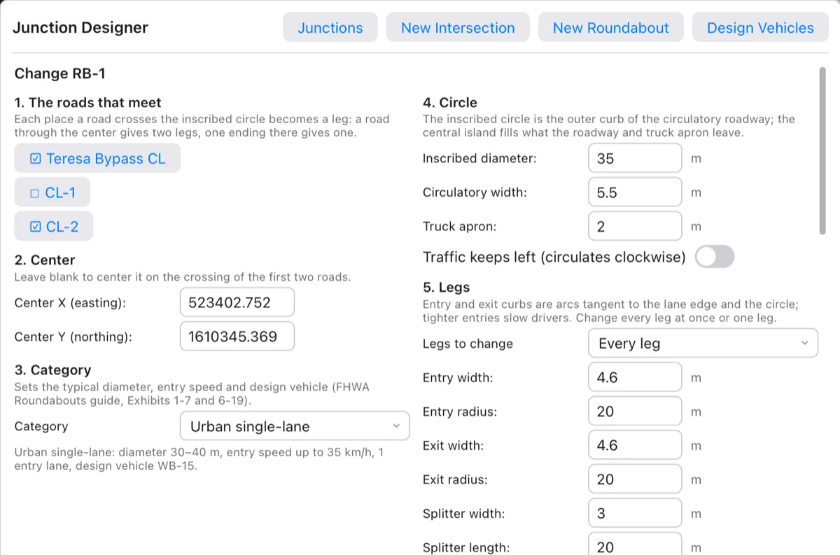
Step 6, Checks, updates as you type: ✗ a check that fails, ! a value outside the typical range, ✓ met. Here the diameter was cut to 28 m: the WB-15 now fails and the size is flagged outside the urban single-lane range.
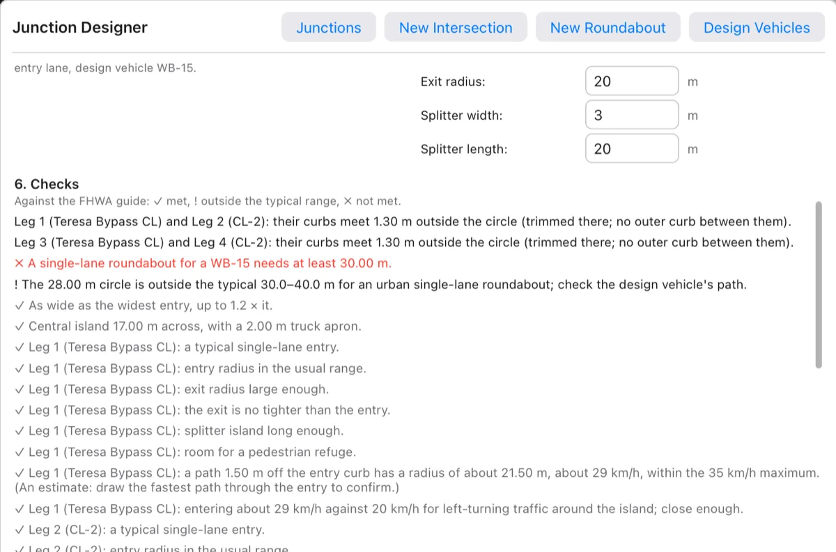
The checks per roundabout: the diameter for the design vehicle and the category's range, the circulatory width against the widest entry (1.0–1.2 ×), the central island and apron, and for every leg the entry width, entry and exit radii, exit no tighter than entry, splitter island width and length, room for a pedestrian refuge, the entry path speed and its difference from the circulating speed. Path speeds are estimates from the curb radii (a path 1.5 m off the curb); the check itself tells you to draw the fastest path through the entry to confirm.
Design Vehicles (junction table)
The Design Vehicles page is the table the junction tools use: Name, Description, Width, Length, Front oh. (front overhang), Wheelbases (tractor first, then kingpin to rear axles, comma separated), Min R (minimum design turning radius, outer front wheel), Inside R and Turns as (the vehicle whose turn-table rows to use when this one has none: BUS-12 and CITY-BUS turn as WB-12, WB-15 as WB-19). At the bottom: Add Vehicle, Reset to AASHTO and Save Vehicles; the table saves with the project.
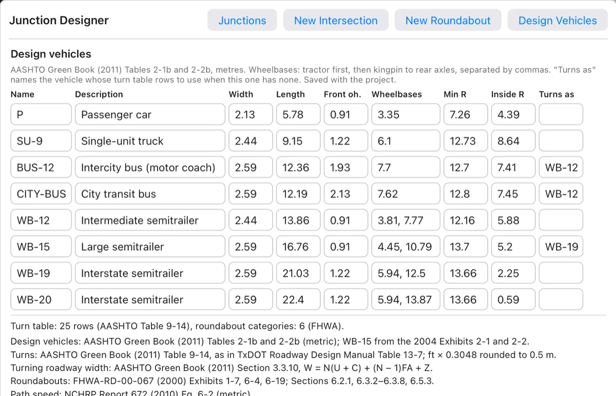
Note The junction tools and the turning paths start from the same AASHTO vehicles, with the same names and sizes, but each keeps its own table: editing one doesn't change the other. The junction table's Min R is the design radius of the outer front wheel (13.7 m for a WB-15); the turning paths' table uses the centerline radius (12.50 m).
How Terrace checks this
Curb return radii, offsets and tapers are AASHTO Green Book (2011) Table 9-14, read from its reproduction in the TxDOT Roadway Design Manual and converted from feet (rounded to 0.5 m). The turn table has no rows for BUS-12, CITY-BUS and WB-15, so those use a larger vehicle's rows and the report says so. Lane widening is the AASHTO 3.3.10 turning roadway width. Roundabout values are FHWA-RD-00-067 (2000), path speeds NCHRP Report 672 Eq. 6-2; the tests compare the widths and speeds against an independent script. Treat the curb returns as a starting point and check the critical turns with a swept path (next section).
Vehicle turning paths
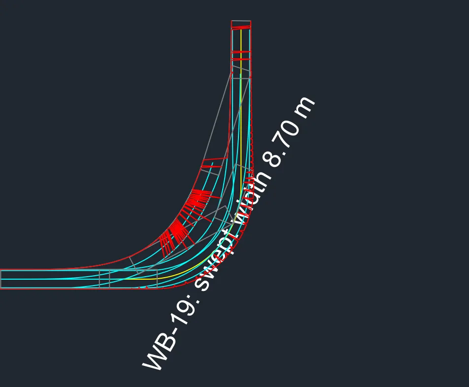
A swept path shows the ground a vehicle covers when it follows a path: its wheel tracks, the outline of its body at intervals and the envelope, the outer edge of everything it sweeps. Long trucks cut corners (their rear wheels run inside the front wheels' path; this is off-tracking), so a swept path is how you prove a WB-15 makes the turn into a junction, a gas station or a loading bay.
Drive a vehicle along a path
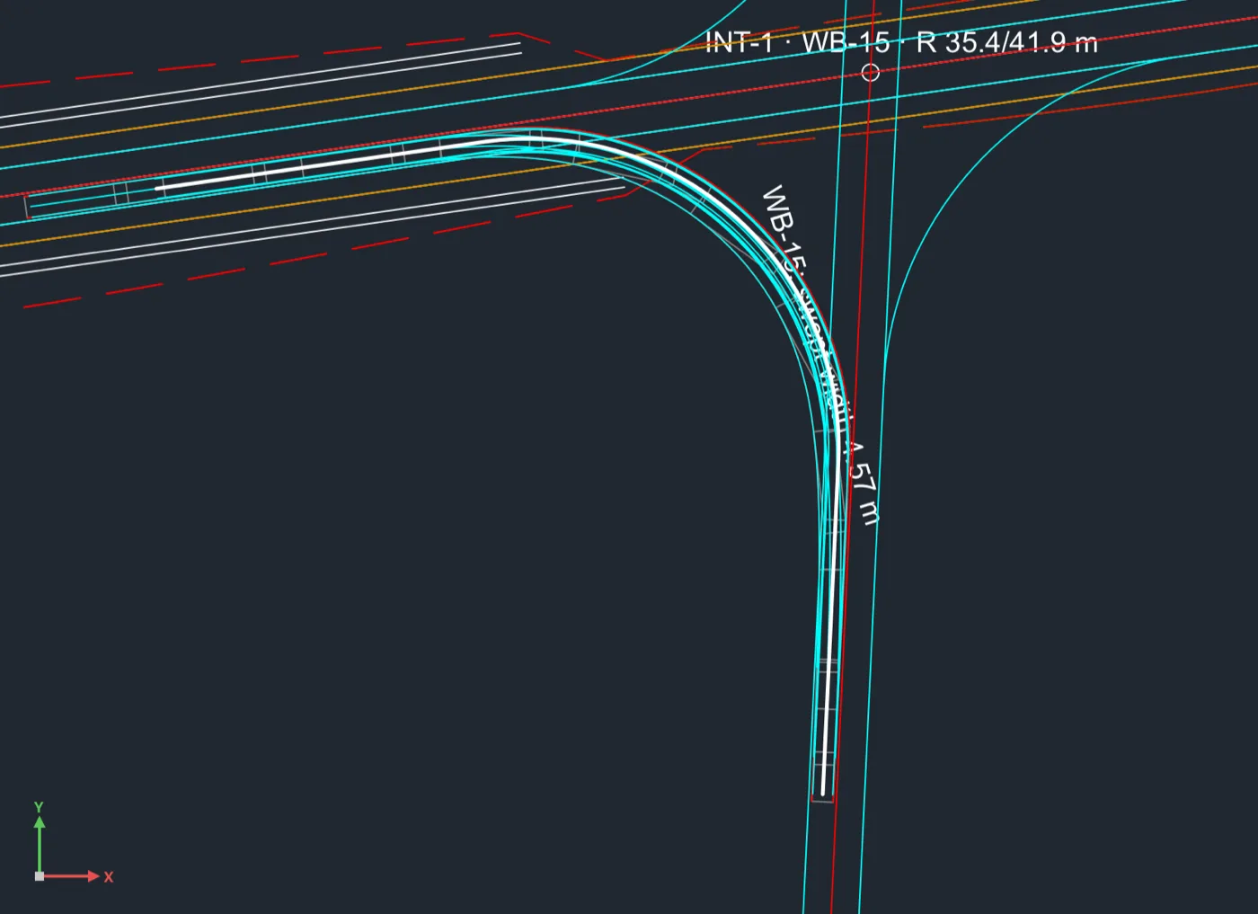
First draw the path the centre of the vehicle's front axle should follow: an alignment, or a polyline, line, arc or spline. Here a polyline follows the middle of the eastbound lane of the Teresa Bypass and turns right into CL-1 on a 37.1 m arc, concentric with INT-1's curb return.
- Click Pro Design ▸ Swept Path (
SWEPTPATH). The log lists the project's vehicles. - At Design vehicle, type a symbol or press Enter for the last one used (WB-15 at first).
- Select the path. Enter takes the selected alignment (or the first one); you can also type an alignment's name.
- For an alignment only: give the Start station and End station (Enter for the whole alignment).
- At Drive which way, choose Forward (from the start of the path) or Reverse.
- At Straight lead-in before the start, give how far the vehicle drives straight before the path begins, so it arrives lined up. The default is 0, or the vehicle's length for an arc.
Terrace simulates the drive and draws it on its own layers (C-SWPT-PATH, -WHEL, -BODY, -ENVL, -TEXT) with a label giving the maximum swept width. The log gives the width and any problem. The path is named after the vehicle (WB-15 path 1).
The swept path report
Swept Path Report (SWEPTREPORT) asks for a path (Enter for the last one) and writes the report to the log and in the Turning Paths window. It gives the vehicle and its dimensions, whether it can follow the path, the length driven, the maximum swept width and where, the tightest bend against the vehicle's minimum turning radius, the steering angle against the steering lock, the off-tracking, and a table of swept width along the path.
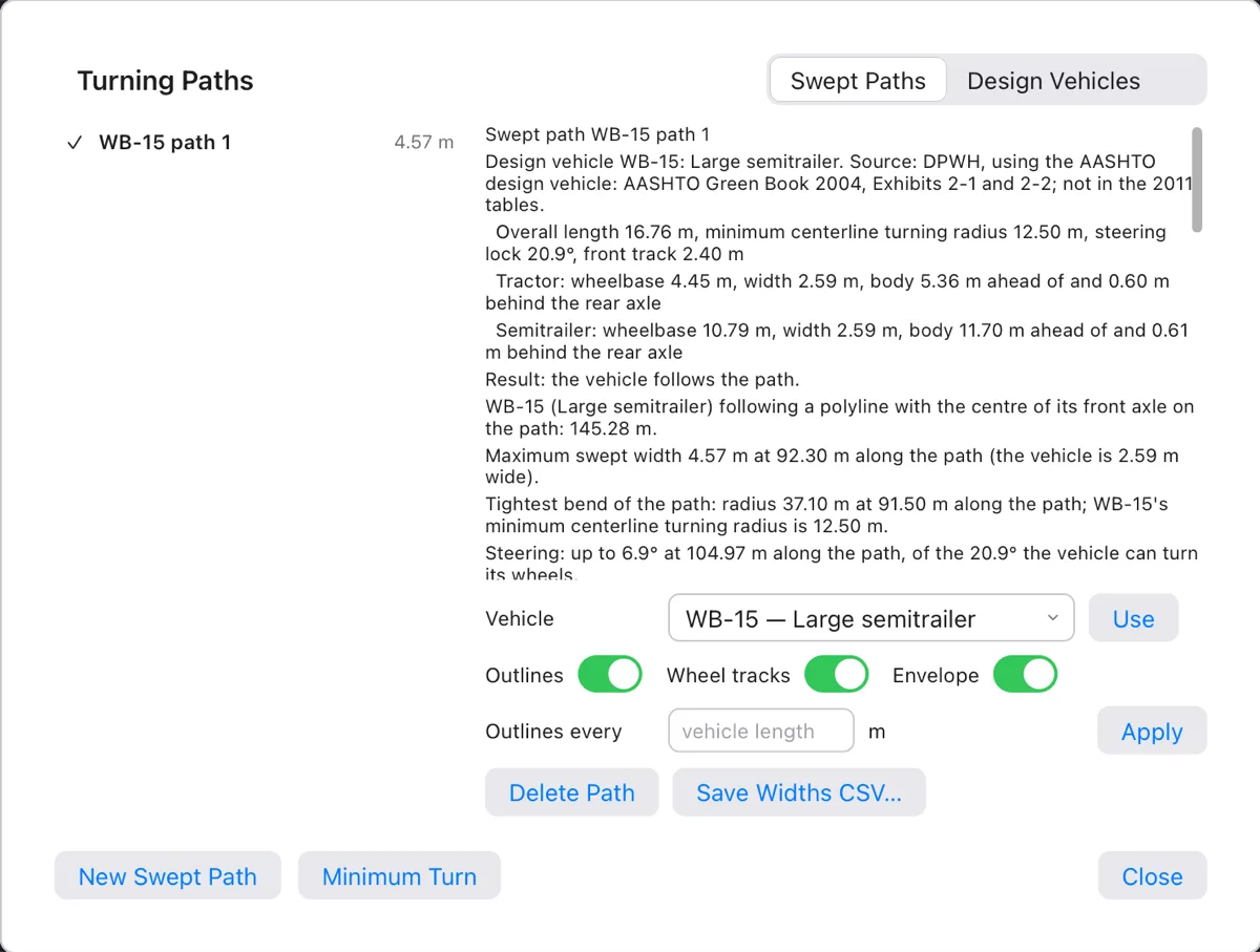
When the vehicle can't make it, the report starts with Result: the vehicle can't follow the path as drawn and lists each problem with a ⚠, for example a bend tighter than the vehicle's minimum turning radius or a steering angle past the lock.
The Turning Paths window
Paths & Vehicles (SWEPTPATHS) opens the window on its Swept Paths tab. The list on the left shows each path with ✓ (it follows) or ⚠ and its maximum width; click one to see its report. Under the report:
| Control | What it does |
|---|---|
| Vehicle + Use | Runs the same path again with another vehicle |
| Outlines, Wheel tracks, Envelope | Which parts are drawn on the plan (click Apply) |
| Outlines every | Distance between body outlines; blank = one vehicle length (click Apply) |
| Delete Path | Removes the path and its graphics (the command is SWEPTDELETE) |
| Save Widths CSV… | Saves the swept width along the path (by station on an alignment) |
| New Swept Path, Minimum Turn | Start SWEPTPATH or SWEPTTEMPLATE |
Minimum turn templates
A minimum turn template is the classic AASHTO turning template: the vehicle turning on its tightest circle. Use it to check a car park, a lay-by or a tight corner quickly.
- Click Pro Design ▸ Minimum Turn (
SWEPTTEMPLATE) and give the vehicle. - Click the Point where the turn begins (front axle centre).
- Give the Direction of approach: click a second point, type an angle, or Enter for 0 (east).
- Give the Turn angle in degrees (+ left, − right), 1° to 360°; Enter takes 90.
The design vehicle table
The Design Vehicles tab of the Turning Paths window holds the vehicles swept paths use. A DPWH project starts with the DPWH set (the AASHTO vehicles used on Philippine national roads: P, SU-9, SU-12, BUS-12, CITY-BUS, WB-12, WB-15, WB-19, WB-20); AASHTO Set loads all 21 AASHTO vehicles (buses, doubles and triples, motor homes and trailers), DPWH Set goes back.
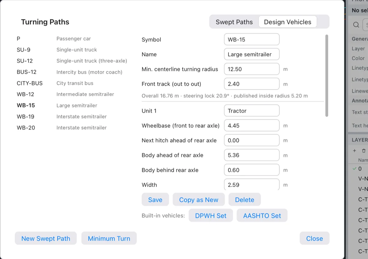
For each vehicle: Symbol, Name, Min. centerline turning radius, Front track (out to out), then per unit: Wheelbase (front to rear axle) (or Hitch to rear axle for a trailer), Next hitch ahead of rear axle (negative = behind), Body ahead of rear axle, Body behind rear axle, Width and Rear track (out to out). The grey line shows the overall length, the steering lock it gives and the published inside radius. Save keeps your changes with the project, Copy as New starts a vehicle of your own from the selected one, Delete removes it.
Check the numbers Some dimensions are assumptions: the tables don't give how far a tractor's frame runs behind its drive axle or the trailer's front ahead of the kingpin, so those are chosen to match the overall length (they only shape the outlines). WB-15 isn't in the 2011 AASHTO tables; its values are the 2004 edition's, and the model gives an inside radius 0.25 m under the published 5.2 m. Check WB-15 work against a current template, and edit any vehicle to match your project's own design vehicle.
How Terrace checks this
Each unit of the vehicle rolls on one equivalent rear axle and is pulled by its leading point, the low-speed "bicycle" (tractrix) model behind AASHTO's templates. A 180° turn at each vehicle's minimum radius reproduces AASHTO Table 2-2b's minimum inside radius within 0.03 m for every single-unit truck and semitrailer (WB-15 aside, above), and the paths agree with an independent ODE integration. It's a kinematic model: it doesn't model speed, tyre slip or a driver's corrections.
Profile optimisation
A grade line decides how much earth the road moves. Profile optimisation lets Terrace try thousands of grade lines within the standard's limits and keep the one with the lowest earthwork and haul cost: excavation, embankment, borrow, waste and overhaul (moving earth beyond the free haul distance, 600 m by DPWH default).
The quick way: Optimize Profile
- Select the road's alignment (in the sample, click Teresa Bypass CL in the Project browser).
- Click Pro Design ▸ Optimize Profile (
OPTIMIZEPROFILE). With nothing selected, it asks for the alignment; Enter takes the first one.
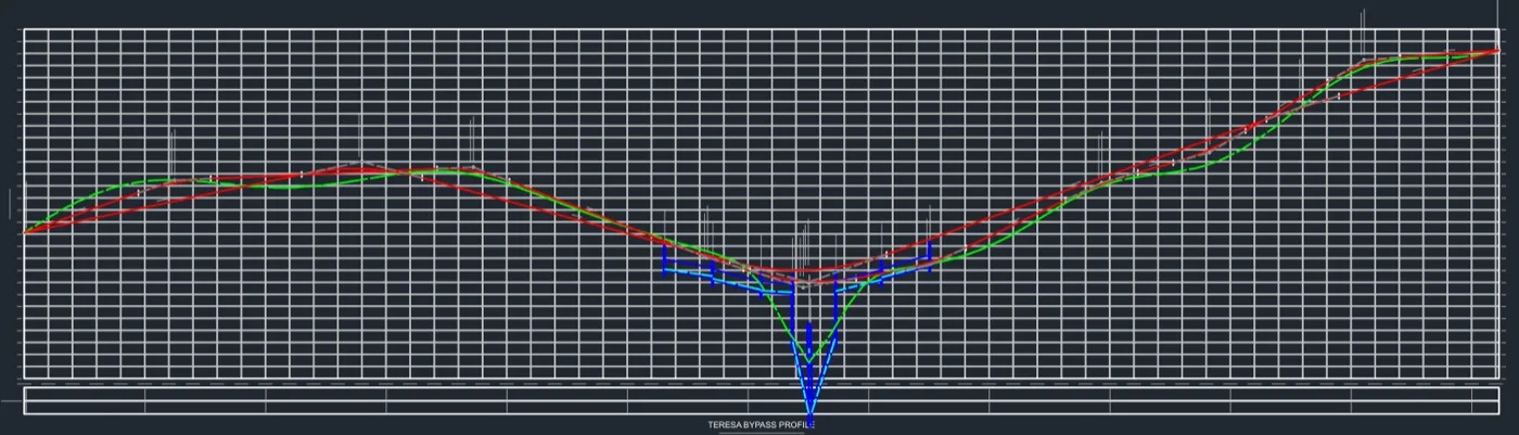
Terrace uses the project's last settings (the defaults at first), makes a new layout profile named <alignment> Optimized (one undo step) and opens the Optimize window on the result. Your own design profile isn't touched; the new one appears in the profile view next to it.
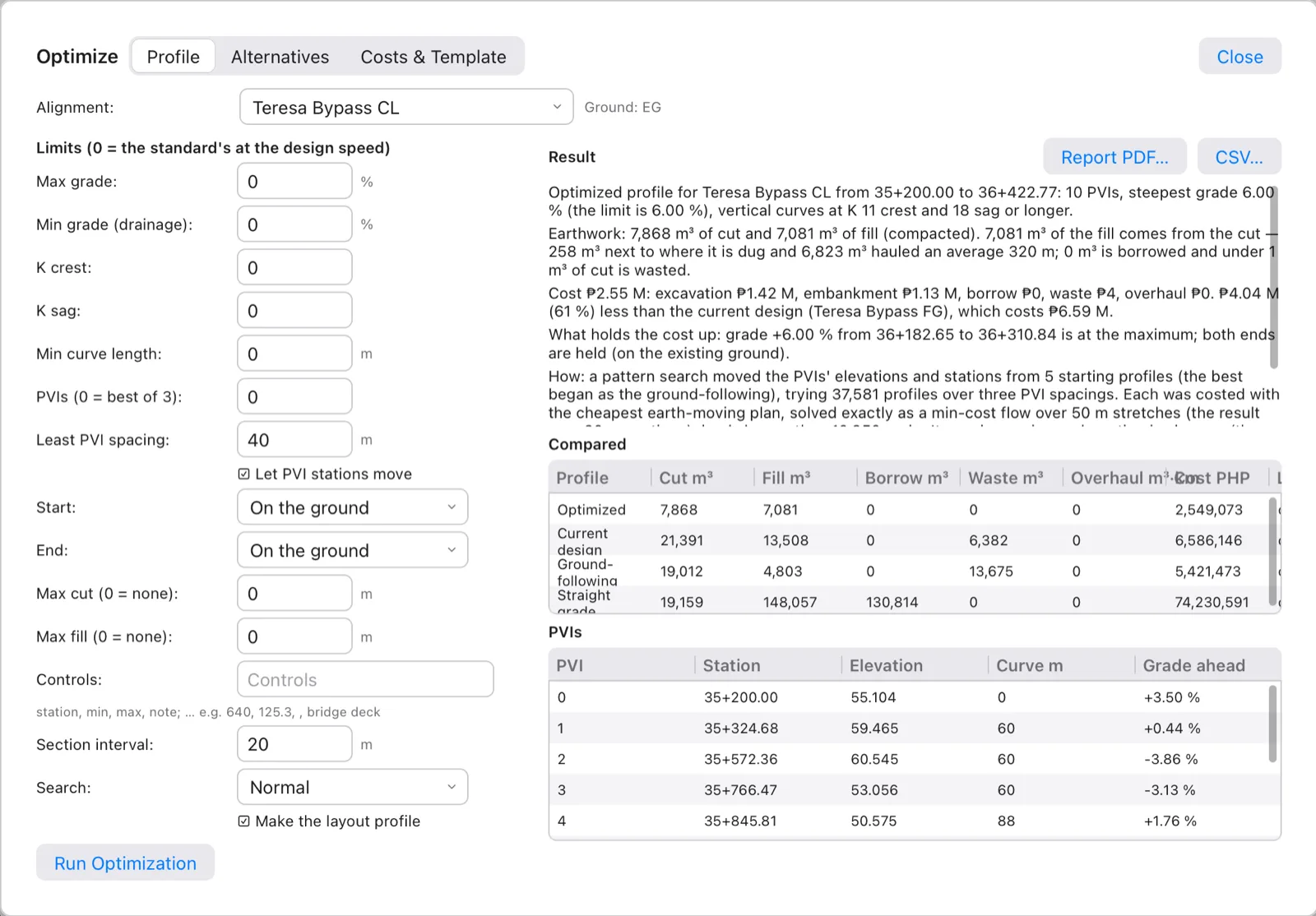
The Result explains what was found in plain words: the PVIs and steepest grade, how much is cut and filled and where it goes, the cost and how it compares with your current design, what holds the cost up (for the sample: "grade +6.00 % from 36+182.65 to 36+310.84 is at the maximum; both ends are held") and how the search went. The Compared table sets the optimized profile against your current design, a ground-following profile and a straight grade (cut, fill, borrow, waste, overhaul, cost and broken limits). PVIs lists the new grade line. Report PDF… and CSV… save it all; Make Profile appears when a run didn't make its profile.
The limits and settings
Open the window with Pro Design ▸ Optimize (OPTIMIZE), pick the Alignment (the line beside it shows which surface is the ground), set the limits and click Run Optimization. Zeros mean "from the standard at the design speed": in the DPWH sample at 60 km/h that's a 6 % maximum grade and K 11 crest / 18 sag.
| Field | Default | What it does |
|---|---|---|
| Max grade | 0 (standard) | Steepest grade allowed, % |
| Min grade (drainage) | 0 (none) | Flattest grade allowed, so water runs off |
| K crest, K sag | 0 (standard) | Least curve length per % of grade change |
| Min curve length | 0 (standard) | Shortest vertical curve, m |
| PVIs (0 = best of 3) | 0 | How many PVIs; 0 tries three spacings and keeps fewer PVIs unless more save at least 0.5 % |
| Least PVI spacing | 40 m | Closest two PVIs may be |
| Let PVI stations move | ☑ | Moves PVIs along the road as well as up and down |
| Start, End | On the ground | On the ground, At an elevation (then give Start elevation / End elevation) or Free |
| Max cut, Max fill | 0 (none) | Deepest cut / highest fill allowed at the centerline |
| Controls | blank | Fixed points: station, min, max, note, separated by ;, e.g. 640, 125.3, , bridge deck (a blank min or max means no bound) |
| Section interval | 20 m | How often the ground is sampled across the road |
| Search | Normal | Quick, Normal or Thorough: more trials take longer and may find a little more |
| Make the layout profile | ☑ | Makes the result a profile; untick to just compare |
If you change the alignment or the surface after a run, the result's heading says (the alignment changed since: run it again).
Costs and the earthwork section
The Costs & Template page holds the unit costs and the cross section used to work out the earthwork. They're saved with the project and used by both optimisation and alternatives.
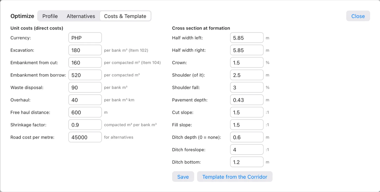
- Unit costs: Currency, Excavation (per bank m³, Item 102; every m³ of cut pays it), Embankment from cut (per compacted m³, Item 104), Embankment from borrow, Waste disposal, Overhaul (per bank m³·km beyond the free haul), Free haul distance, Shrinkage factor (compacted m³ one bank m³ of cut makes; 0.9 = 10 % shrink, above 1 for rock that bulks) and Road cost per metre (everything besides earthwork, used only to compare alternatives).
- Cross section at formation (the subgrade the earthworks build): half widths, crown, shoulder and its fall, pavement depth (formation = design grade − depth), cut and fill slopes, and an optional ditch in cut (depth, foreslope, bottom width).
By default the section follows each alignment's corridor (or its road class when it has none). Save keeps the values you typed for every alignment; Template from the Corridor goes back to following the corridors.
Use your own unit costs The default costs are typical 2024–2026 DPWH figures for illustration only. Put in your project's own before you trust a cost or a ranking.
Alignment alternatives
Sometimes moving the road is cheaper than reshaping its grade. Alternatives generates variants of an alignment, optimizes a profile along each over the same ground, and ranks them by total cost: earthwork and haul plus the length × the road cost per metre.
- Select the alignment and click Pro Design ▸ Alternatives (
ALIGNALTERNATIVES), or open the Optimize window's Alternatives page and click Compare. - Read the ranking in the log or the window. The variants are drawn on the plan.
The variants are: each interior PI moved either way across the line (PI 1 inside, PI 1 outside…), the radii eased and tightened (Radii eased, Radii at minimum), and a combination of the PI moves that paid. On the Alternatives page you can set Move PIs by (0 = auto) and untick Ease and tighten radii or Combine the moves that pay before you click Compare.
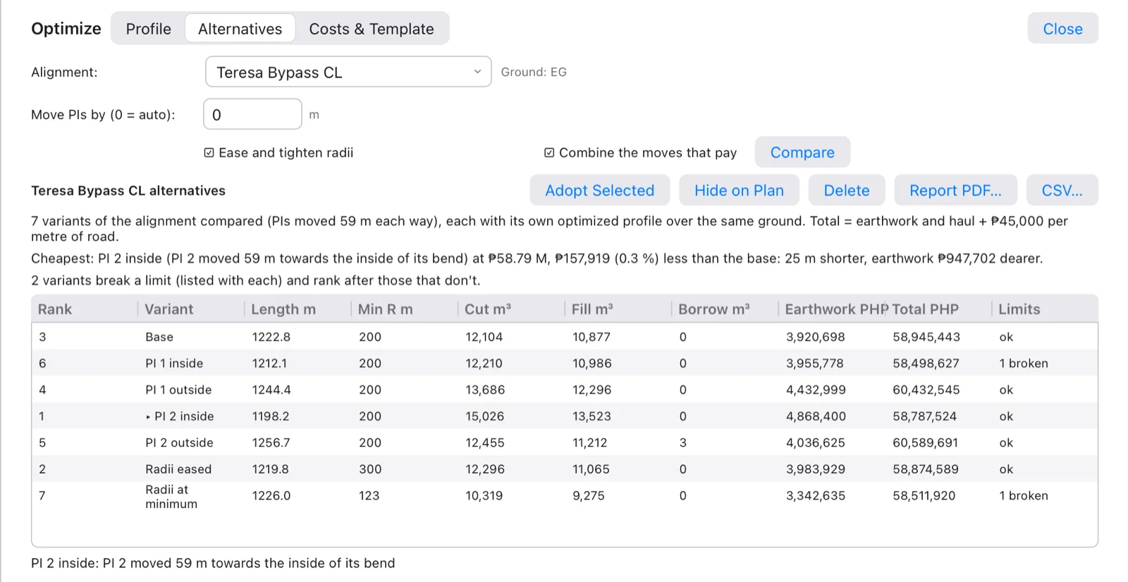
Click a row's rank or name to select it: the line under the table says what that variant is, which limits it breaks and its notes, and the plan draws it as the chosen variant (each choice is an undo step). Variants that break a limit (a radius below the minimum, a grade too steep) rank after those that don't. The buttons: Adopt Selected, Show on Plan / Hide on Plan, Delete (the study), Report PDF… and CSV….
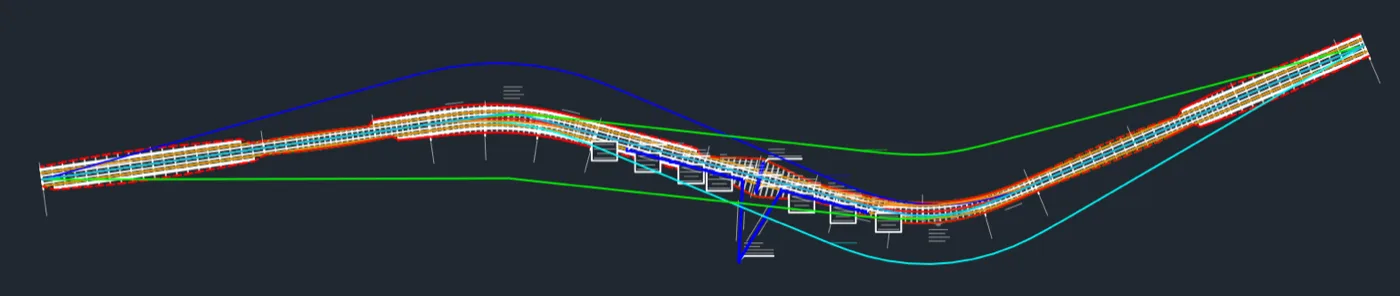
C-ROAD-OPTM-ALTS and C-ROAD-OPTM-BEST).Adopting a variant
To make a variant a real alignment, select it and click Adopt Selected, or click Pro Design ▸ Adopt Alternative (ADOPTALTERNATIVE) and give its rank in the last study (Enter takes the selected one, else rank 1). Terrace makes an alignment named <base> Alt <rank> with its ground profile and its optimized design profile. Place a profile view for it with CREATEPROFILEVIEW. Your original road stays as it was.

How it works, and its limits
For each trial profile Terrace reads the cut and fill areas at every section from tables made once per station, so a trial is cheap. Where the earth goes is solved exactly as a min-cost transportation problem, the linear programme a mass haul diagram approximates: it respects the free haul and finds the limit of economic haul itself. The tests check the section areas against shapely and the earth plan against SciPy's linear programming solver (HiGHS).
Choosing the PVIs is different: it's a pattern search (moves of one PVI, two neighbours, the whole line and PVI stations, with shrinking steps) started from several profiles, with a large penalty for any broken limit. That's a good heuristic, not a proof: the result is the cheapest profile the search found, not a guaranteed optimum, and a different start or a Thorough search can find a slightly different one. During the search the haul is worked out over 50 m stretches; the final result is costed again at full resolution.
- The earthwork section is a simple template at formation level, not the corridor itself: for the final quantities, build the corridor on the profile you choose and compute volumes (Sections and earthwork).
- Alternatives use the Quick search for every variant, so the base variant's earthwork can be higher than an Optimize Profile run on the same road.
- Only PI moves and radii are tried; Terrace doesn't search for whole new routes.
The 3D view
The 3D view shows the project as a model: surfaces coloured by elevation with contours, the corridor's finished road with its pavement, shoulders and side slopes, pipes and structures, alignments and their stations. It's the fastest way to see whether a design sits well in the ground, and to show it to people who don't read plans.
- Click Pro Design ▸ 3D View (
VIEW3D). - The 3D view opens as a pane over the lower right of the plan, so you keep the plan in sight. Click Larger to make it fill most of the window (Smaller to go back) and × to close it.
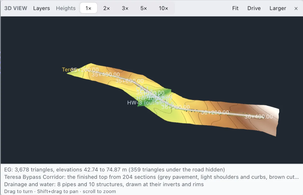
Move around with the mouse: drag to turn the model, Shift+drag (or drag with the right button) to pan, scroll or pinch to zoom. Fit shows the whole project again. The lines under the model say what's shown. The view builds itself again whenever the project changes.
Vertical exaggeration
Roads are long and gentle, so at true scale a 6 % grade hardly shows. Heights stretches every elevation: 1× (true scale, the default), 2×, 3×, 5× or 10×. For any other value use Pro Design ▸ Exaggeration (EXAGGERATION3D) and type 0.1 to 50.
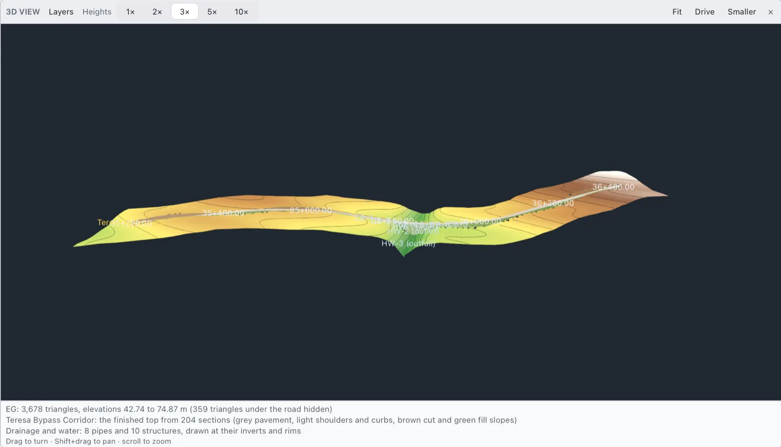
What's shown
Click Layers for the side panel:
- CONTOURS: None, Major (each surface's major interval, the default) or All.
- See-through ground: makes the ground translucent so the pipes under it show.
- SHOW: one line per surface (with its triangle count and elevation range), the corridor's road, the corridor's feature lines, pipes and structures, alignments, feature lines, points (off by default) and labels. Click a line to turn it on or off. Surfaces made by a corridor are off at first, and the ground's triangles under the road are hidden so the road doesn't disappear into a cut.
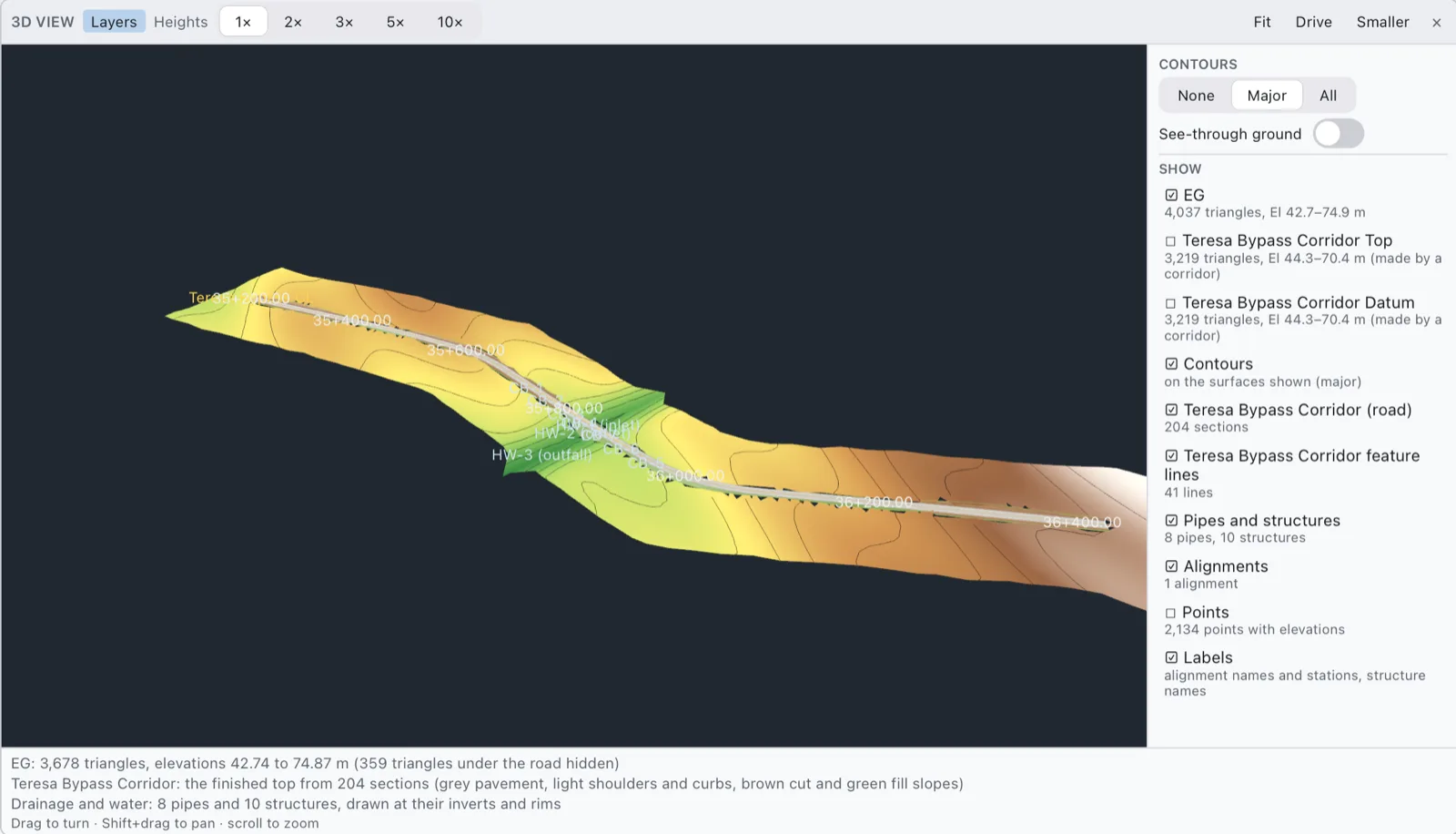
The exaggeration, contours, see-through ground and layers are kept in the project, and each change is one undo step. The camera isn't saved.
The drive-through
A drive-through puts you in the driver's seat: the eye moves along the road at a driver's eye height on the finished road and looks ahead into the curves and over the crests. It's a quick way to feel sight distance and the flow of the alignment.
- Click Pro Design ▸ Drive-Through (
DRIVE), or Drive in the 3D view's bar. - At Select alignment to drive along, press Enter for the road (the selected alignment, else the first centerline with a design profile) or pick another. Before that you can type
Sfor Speed (km/h, 0 = the alignment's design speed) orEfor Eye height (1.08 m for a car, AASHTO; about 2.4 m for a truck). - The 3D view opens and starts driving.
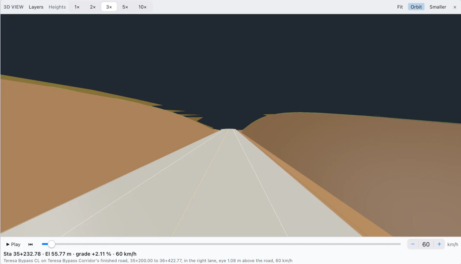
The drive bar under the view:
| Control | What it does |
|---|---|
| ▶ Play / ❚❚ Pause | Drives on or stops; at the end it stops, and Play starts again from the beginning |
| ⏮ | Back to the start |
| Station slider | Drag to jump to any station |
| Speed | 10 to 150 km/h in steps of 10 |
| Alignment menu | Shown when the project has more than one alignment: drive another one |
The bold line reads the station, road elevation, grade and speed as you go; the line under it describes the drive. The eye is in the middle of the right lane (half the lane width right of the centerline). When the alignment has a corridor, the eye rides on the corridor's finished top, so superelevation tilts the view; without one it rides on the design profile. It looks 40 m ahead.
Click Orbit to stop driving and turn the model again; dragging in the view does the same, centred where the driver was. The speed and eye height you give DRIVE are kept in the project; the speed in the drive bar is only for this drive.
Note The drive needs a profile: an alignment without one says so and doesn't drive. The eye's lane offset and look-ahead distance can't be changed in this version.