
Sheets and plotting
This chapter takes a finished road design to paper: view frames along the alignment, plan-and-profile sheets with match lines and a filled-in title block, cross-section sheets, and PDF files of them all. By the end you'll be able to produce a full plan set for the Teresa Bypass Road on A1 or on the Philippine 20×30 sheet and export it as one multi-sheet PDF.
How plan production works
Plan production in Terrace has two steps:
- View frames: rectangles along the alignment, each the size of a sheet's plan area at the plan scale, turned to follow the road. Consecutive frames overlap a little, and a match line across the road marks where one sheet ends and the next begins.
- Sheets: one paper layout per frame, with the plan turned so the road runs across the sheet, the profile of the same stations below it, and a title block.
The sheets are ordinary layouts (the tabs under the drawing), with live viewports into the model. Edit the design and the sheets show the change; you never redraw a sheet by hand.
The tools are in the Plan Production group of the Sheets tab:

| Button | Command (aliases) | What it does |
|---|---|---|
| View Frames | VIEWFRAMES (VFRAMES, FRAMES) | Opens the Plan and Profile Sheets dialog: view frames along an alignment for a sheet size and scale, and their layouts (typed: frames only, at the command line) |
| Plan & Profile Sheets | CREATESHEETS (SHEETS, PLANPROFILE) | Makes a plan-and-profile layout for every view frame |
| Section Sheets | SECTIONSHEETS (XSHEETS) | Arranges the cross sections of a sample line group on sheets |
When the road is built, the Next step panel also offers Make plan & profile sheets, which opens the Plan and Profile Sheets dialog, or runs CREATESHEETS once the frames exist.
Sheet sizes and scales
Terrace knows these sheet sizes, all landscape:
| Family | Sizes (mm) |
|---|---|
| ISO | A0 1189 × 841, A1 841 × 594 (the default), A2 594 × 420, A3 420 × 297, A4 297 × 210 |
| Philippine | Philippine 20x30: 762 × 508 (20 × 30 in), the sheet many DPWH plans use |
| ANSI | ANSI A 279.4 × 215.9, B 431.8 × 279.4, C 558.8 × 431.8, D 863.6 × 558.8, E 1117.6 × 863.6 |
| ARCH | ARCH A 304.8 × 228.6, B 457.2 × 304.8, C 609.6 × 457.2, D 914.4 × 609.6, E 1219.2 × 914.4 |
When you type a size, case and spaces don't matter: a1, Philippine 20x30 and ANSI D all work.
The plan scale is typed as the number after "1:". The default is 1:1000, usual for DPWH plan-and-profile sheets; the profile's vertical scale follows the profile view's exaggeration, so the sample's sheets read H 1:1000 V 1:100.
Making view frames
The quickest way from a finished road to sheets is the dialog: it makes the frames and, if you like, the sheet layouts in one step.
The Plan and Profile Sheets dialog
- Select the alignment (or a profile or profile view of it) if the project has several, and click Sheets ▸ View Frames. The Plan and Profile Sheets dialog opens on that alignment.
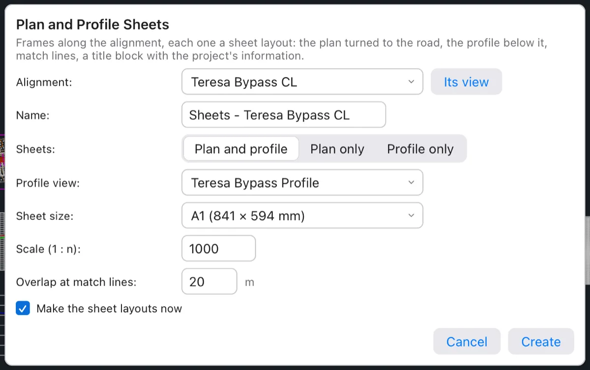
The Plan and Profile Sheets dialog with its defaults on the sample project. - Check the fields:
- Alignment: the road the frames follow. Its view picks that alignment's profile view again after you change the alignment.
- Name: Sheets - Teresa Bypass CL by default; the layouts are named after it.
- Sheets: Plan and profile (the default), Plan only or Profile only.
- Profile view: the alignment's profile view the sheets' profiles come from. If the alignment has none yet, the dialog says so; make one, or choose Plan only.
- Sheet size: every size in the table above, A1 by default (ANSI D in US projects).
- Scale (1 : n): 1000 (600 in US projects), and Overlap at match lines: 20 m (50 ft).
- Make the sheet layouts now: ticked, so the layouts are made at once and you don't need
CREATESHEETS.
- Click Create. On the sample the command line answers 2 view frames, 2 sheet layouts along Teresa Bypass CL., and the tabs Sheets - Teresa Bypass CL - 1 and - 2 appear under the drawing.
The dialog always makes a new view frame group (with a free name), even when the alignment already has one; delete the old group in the Project browser if you don't need it.
By the command line
- Type
VIEWFRAMES(VFRAMES,FRAMES). - Select alignment for the sheets: press Enter for the alignment shown, click one, or type its name. Type D (Dialog) to open the Plan and Profile Sheets dialog instead. If the alignment has no profile view yet, Terrace tells you the sheets will be plan only.
- Sheet size (A0–A4, ANSI A–E, ARCH A–E, Philippine 20x30) <A1>: type a size or press Enter.
- Plan scale 1: <1000>: type the scale or press Enter.
Terrace reports what it made: Plan and Profile: 3 view frames on Philippine 20x30 at 1:1000. CREATESHEETS makes the layouts. The sample's 1.22 km road needs two A1 sheets at 1:1000, or three of the smaller 20×30 sheets.
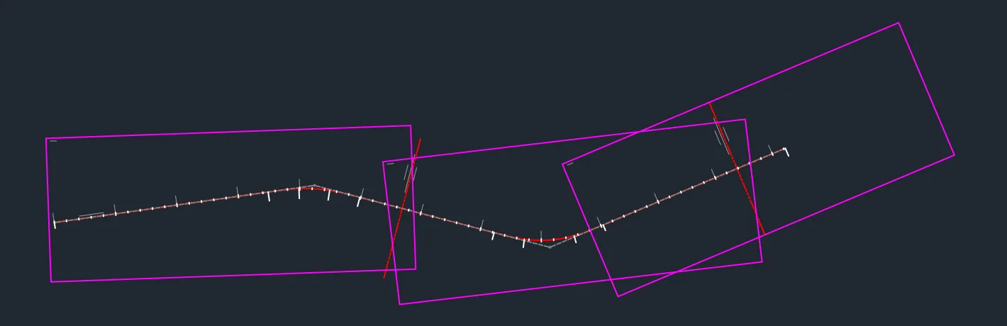
With the command, each alignment has one view frame group: running VIEWFRAMES again on the same alignment remakes its frames with the new size and scale, and the sheet size and scale you used are remembered. New groups are named after the alignment and listed under View Frame Groups in the Project browser (the sample's is called Plan and Profile).
Watch out After remaking the frames, run CREATESHEETS again: the layouts made from the old frames are emptied until you do.
View frame properties
Select the group in the Project browser to change it in Properties:
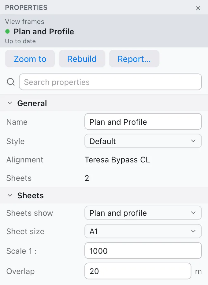
- Sheets show: Plan and profile (the plan in the top half, the profile in the bottom), Plan only (the plan fills the sheet) or Profile only.
- Sheet size and Scale 1 :: as above.
- Overlap: how far each frame runs past the match line into the next one, so the plan shows a little context on both sides. The sample uses 20 m.
The frames are rebuilt when you change these. Then run CREATESHEETS to remake the layouts.
Plan-and-profile sheets
- Click Sheets ▸ Plan & Profile Sheets, or type
SHEETS. (If there are no view frames yet, Terrace tells you to runVIEWFRAMESfirst.) - Select view frame group: press Enter for the group shown, or pick one.
Terrace makes one layout per frame, named after the group: Plan and Profile - 1, Plan and Profile - 2… and says 3 sheets made (1 new layout). Running it again replaces the layouts it made before, and only those, so your own layouts are safe.
Click a sheet's tab under the drawing to see it:
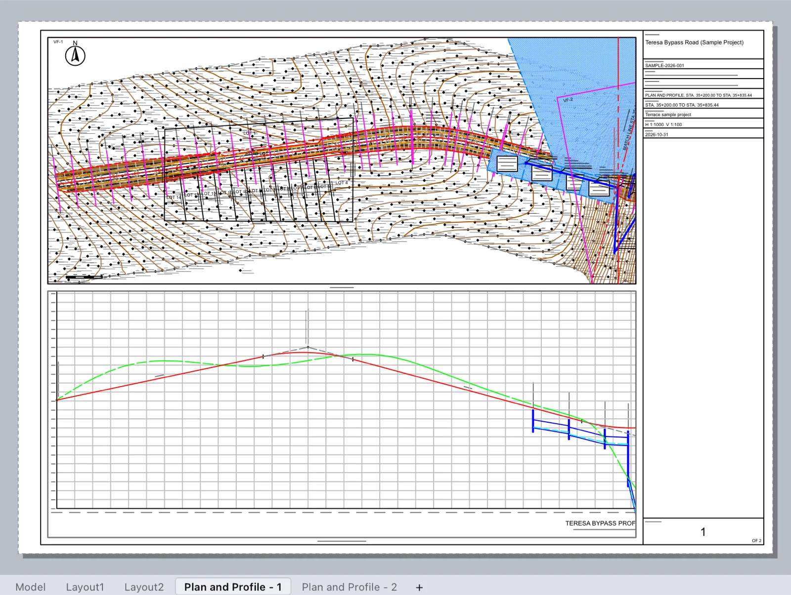
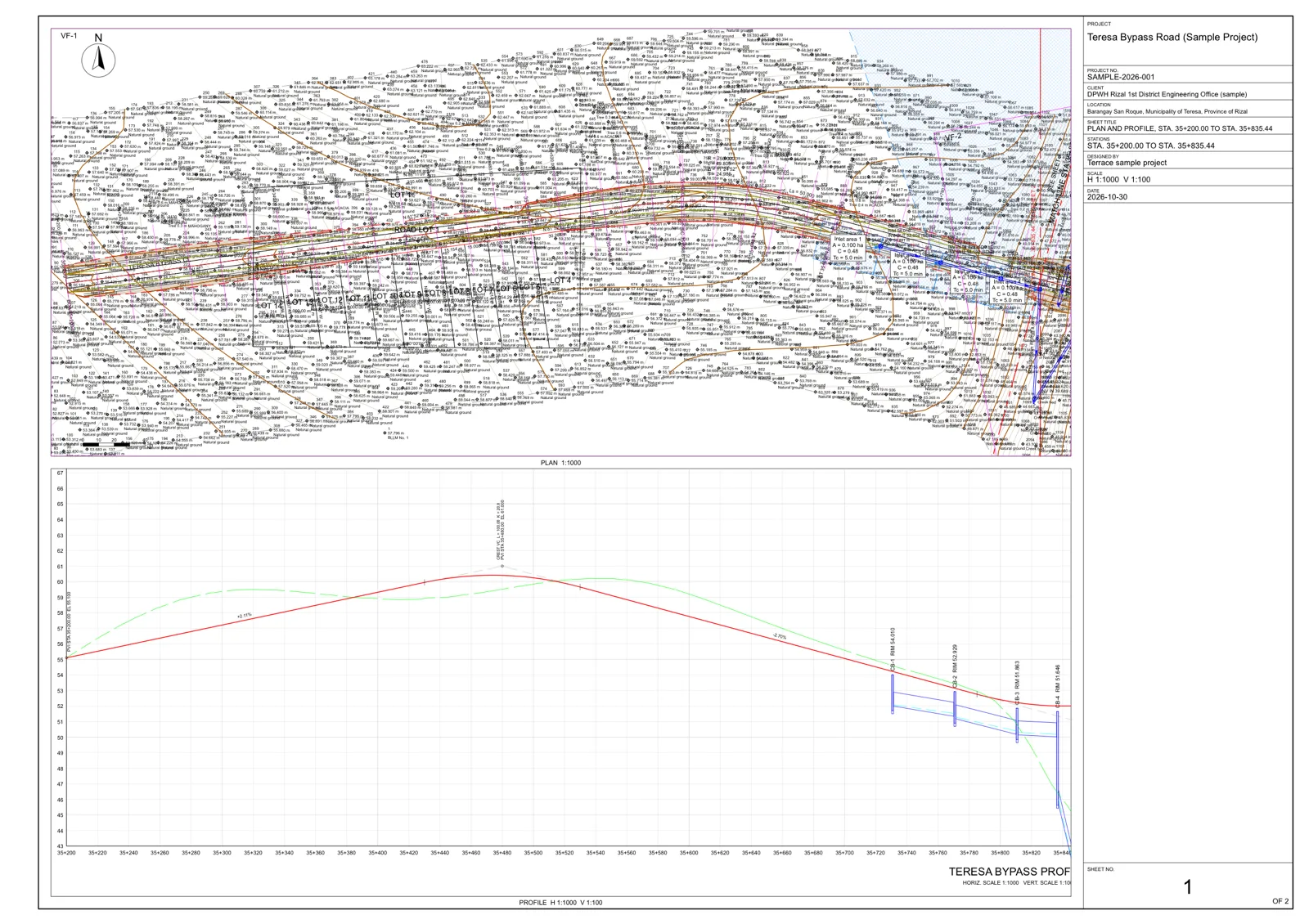
Each sheet has:
- A border with a 25 mm binding margin on the left (15 mm on sheets smaller than A2) and 10 mm on the other sides (7 mm on small sheets).
- The plan viewport, turned so the road runs left to right, titled PLAN 1:1000 beneath, with a north arrow in its top-left corner (pointing north whatever the turn) and a scale bar at its bottom left.
- Match lines where the sheet joins its neighbours, each labelled MATCH LINE STA. 35+835.44 - SEE SHEET 2.
- The profile viewport over the same stations, titled PROFILE H 1:1000 V 1:100, centred on the profiles' elevations in that range.
- The title block down the right side, with the sheet number and OF 2 at its foot.
Viewports and the title block are on their own layers: G-ANNO-VPRT (viewports, not plotted), G-ANNO-TTLB (border and title block) and C-ANNO-MTCH (match lines).
The title block
The title block is filled from the project's information. Set it once in Sheets ▸ Project Settings (Project name, Project number, Client / owner, Location, Designed by) before you make the sheets.
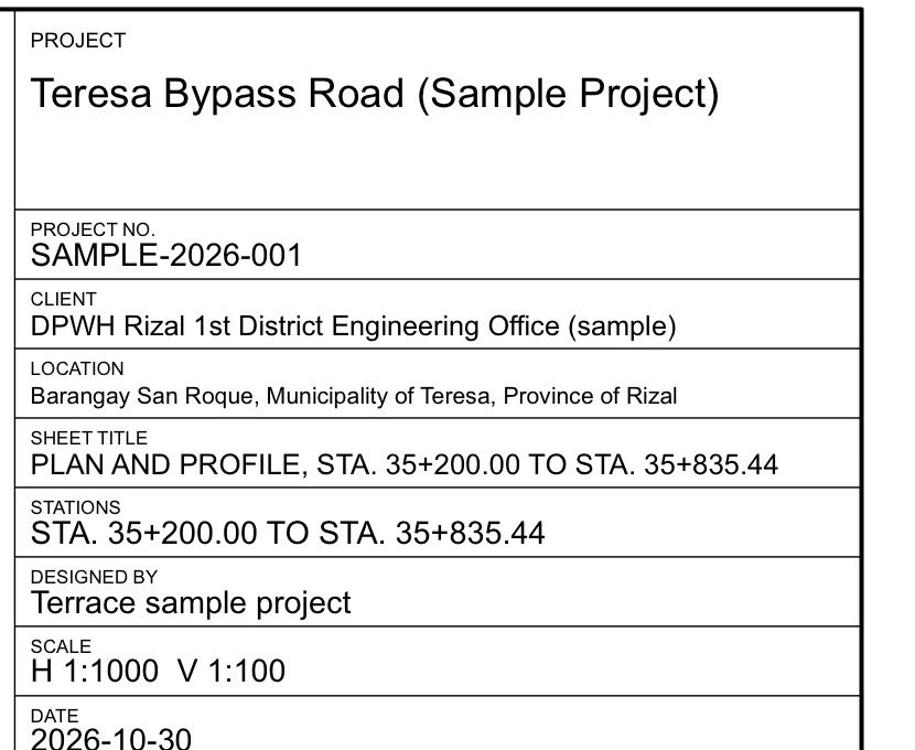
| Row | Filled with |
|---|---|
| PROJECT | Project name |
| PROJECT NO. | Project number |
| CLIENT | Client / owner |
| LOCATION | Location |
| SHEET TITLE | PLAN AND PROFILE STA. … TO STA. … (or PLAN, PROFILE for the other sheet kinds) |
| STATIONS | STA. start TO STA. end of the sheet |
| DESIGNED BY | Designed by |
| SCALE | H 1:1000 V 1:100 on plan-and-profile sheets, else the plan scale |
| DATE | The day the sheets were made |
| SHEET NO. | The sheet's number and OF n |
Note A view frame group keeps the project name it was made with, and the sample's group also has its own sheet title. Re-make the view frames after renaming the project if the PROJECT line must change.
Cross-section sheets
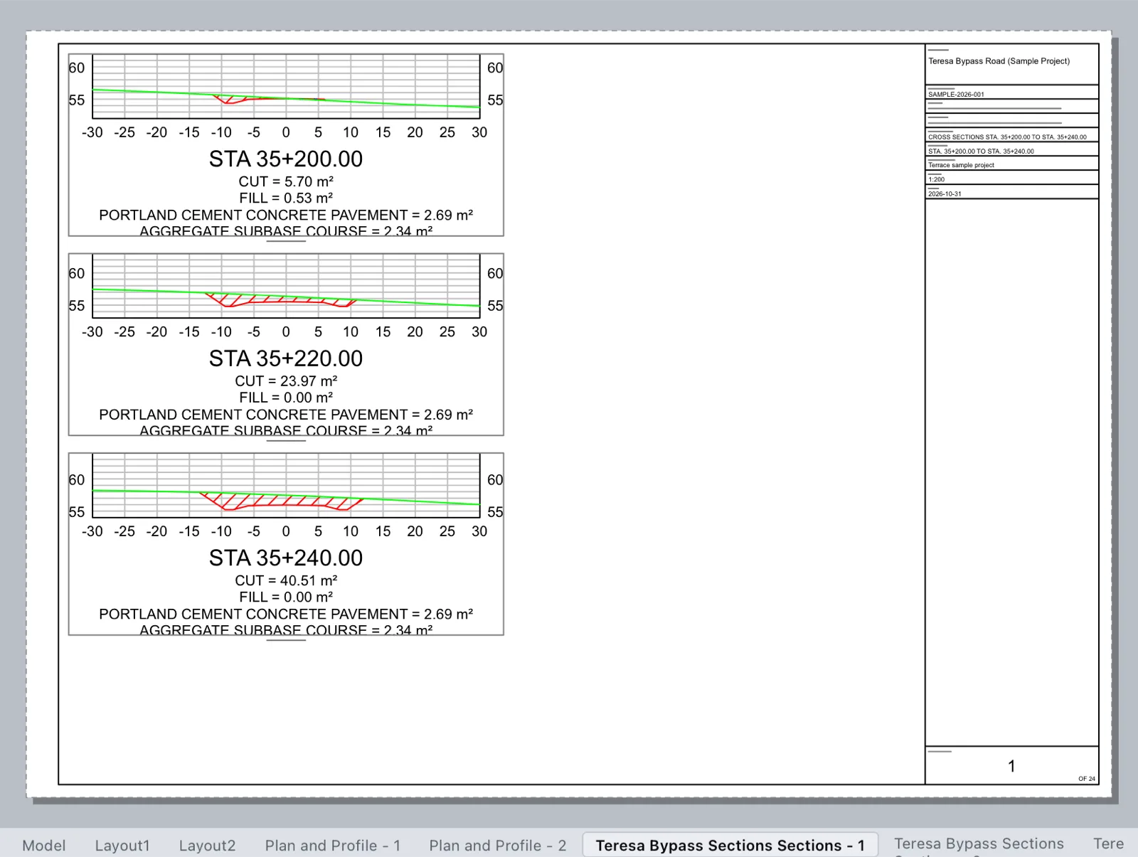
Cross-section sheets show the sections cut by a sample line group (see Sections and earthwork) stacked on sheets, each with its station, cut and fill areas and the areas of the pavement materials.
- Click Sheets ▸ Section Sheets, or type
XSHEETS. - Select sample line group: press Enter for the group shown, or pick one.
- Sheet size … <A1>: type a size or press Enter.
- Section scale 1: <200>: 1:200 is the usual DPWH section scale.
Terrace says how many it made (24 section sheets made. for the sample on A1 at 1:200). The layouts are named after the group, such as Teresa Bypass Sections Sections - 1.
The layout tabs
Every sheet is a layout tab under the drawing, after Model. Click a tab to open the sheet; the status bar switches from MODEL to PAPER and a Layout ribbon tab appears. Right-click a tab for Rename, Delete, Move or Copy…, Page Setup Manager… and Plot….
You can add your own notes, details and legends to a sheet like on any layout (see Drafting). Keep them off the sheet's own layers, because CREATESHEETS replaces what it made when you run it again.
Plotting and PDF
Terrace plots with the plot tools it shares with its drafting side.
One sheet
- Open the sheet's tab.
- Click Output ▸ Plot (⌘P) or Output ▸ Export PDF, or right-click the tab and choose Plot….
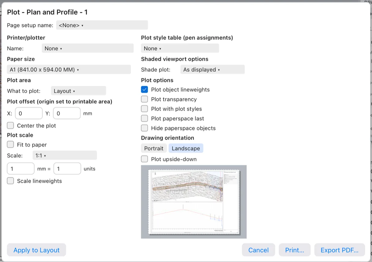
- Check the dialog: the paper size is already the sheet's (Philippine 20x30 (762.00 x 508.00 MM) here), What to plot is Layout, the scale 1:1, landscape. The preview shows the sheet.
- Click Export PDF… and choose where to save it, or Print… to send it to a printer.
Here is the sample's first sheet exported as a PDF, at full A1 size and in vector, so text stays sharp at any zoom:
The whole set
To get every sheet in one file, use Output ▸ Publish:
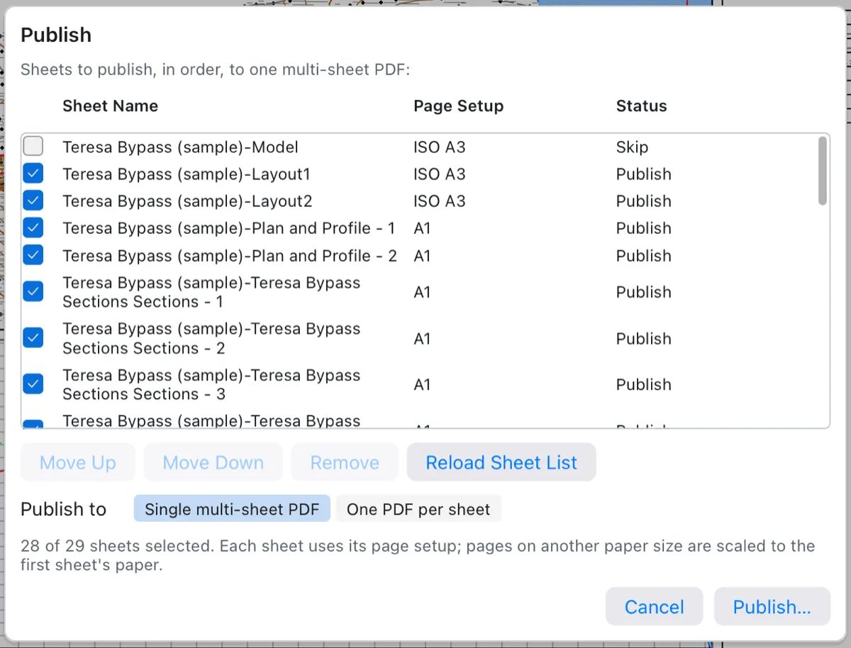
- Untick the layouts you don't want (the sample's Layout1 and Layout2 are leftovers you can skip), and use Move Up / Move Down to order the sheets.
- Choose Single multi-sheet PDF or One PDF per sheet.
- Click Publish… and choose the file or folder.
Each sheet is plotted with its own page setup. In a single PDF, sheets on another paper size are scaled to the first sheet's paper. After making new sheets, click Reload Sheet List.
More on plot settings, page setups and plot styles is in Drafting.