
Drafting
Terrace is a full 2D CAD program as well as a civil design tool: its drafting side comes from Draftwork and works like AutoCAD. This chapter tours the Draft, Annotate, View and Output tabs, the status bar toggles, layers and layouts, and explains how your own linework and the civil objects live together in one drawing.
Drafting in a civil project
Every Terrace project is also an ordinary drawing. Next to the civil objects you can draw lines, polylines, text, dimensions, hatches and blocks — a borrow area, notes for the contractor, a title block, a detail. They save in the .terrace file and go out with the plan to DWG, DXF and PDF.
The drafting tools sit on the four tabs after the task tabs: Draft, Annotate, View and Output. Every button runs a command, so if you know AutoCAD you can type the same names and aliases on the command line: LINE (L), PLINE (PL), MOVE (M), TRIM (TR)… Hover over a button to see its command and alias. The full list is in the command reference.
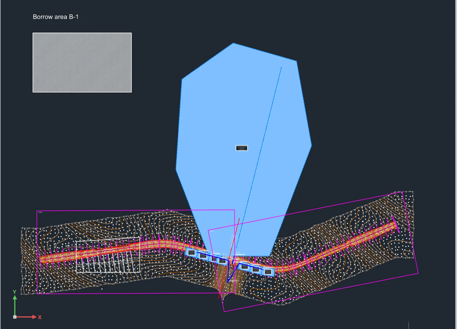
RECTANG, HATCH and TEXT beside the Teresa Bypass Road.The Draft tab
The Draft tab holds what you use most: drawing, editing, layers, properties and blocks.

| Group | Buttons |
|---|---|
| Draw | Line, Polyline, Circle, Arc, Rectangle, Polygon, Ellipse, Hatch, Gradient, Spline. |
| Modify | Move, Copy, Stretch, Rotate, Mirror, Scale, Trim, Fillet, Array, Erase, Explode, Offset. |
| Annotation | Text (multiline), Dimension, Leader. |
| Layers | Layer Properties (shows the Layers panel), the current-layer list, Isolate, Unisolate, Off, Freeze, Make Object's Layer Current, Layer States. |
| Properties | Match Properties, and the color, linetype and lineweight lists for new objects (or the selected ones). |
| Block | Insert (the Blocks palette), Create, Attribute. |
| Utilities | Measure (distance), Quick Select, Select All, ID Point. |
Drawing
- Click a Draw button, or type its command and press Enter (for a polyline:
PL). - Click points in the plan, or type coordinates on the command line (
523800,1610950, or@50,0relative to the last point, or@50<30for 50 m at 30°). - Answer the options in brackets by typing their capital letters (
Afor Arc in a polyline,Cto close), and press Enter to finish.
The prompts are the AutoCAD ones, shown on the command line above the input. Esc cancels, and Enter on an empty command line repeats the last command.
Editing
Select objects first (click, or drag a window: left to right takes what's fully inside, right to left what it touches), then start the command — or start the command and select when it asks "Select objects:". Grips (the small squares on a selected object) stretch and move it directly. See Selecting and editing for selection in general.
The Annotate tab: text, dimensions, tables

- Text: Multiline Text (
MTEXT,T) and Single Line (TEXT,DT); Text Style; Find Text; Field (live values such as the date or a sheet number); Check Spelling. - Dimensions: Dimension (
DIM, picks the kind from what you click), Linear, Aligned, Angular, Radius, Diameter, Ordinate, Arc Length, Continue, Baseline, and Dim Style. - Tables: Table and Table Style.
- Leaders: Multileader (
MLEADER) and Quick Leader. - Annotation Scaling: Scale List, and adding or removing scales on annotative objects so a note reads the same size at 1:500 and 1:1000.
- More Drafting: menus with the rest of the drawing tools (Wipeout, Revision Cloud, Donut, Construction Line, Ray, Boundary, Point, Divide, Measure, Region), region tools (Union, Subtract, Intersect, Mass Properties), blocks (Write Block, the Blocks palette's Recent, Favorites and Libraries, Block Editor, attributes) and groups (Group, Ungroup, Group Manager, Group Selection).
Text heights are in drawing units: in a metric project at 1:1000, text 2.5 mm high on paper is 2.5 m in the plan. Civil labels size themselves from the drawing scale in Project Settings; your own text doesn't, unless it's annotative.
Hatches
Draft ▸ Hatch (HATCH, H) fills an area: click inside a closed outline (Terrace finds the boundary, islands included) and press Enter. Type T (seTtings) at the prompt to open the Hatch dialog, where you pick the pattern from a list with a sample, its scale and angle. Gradient fills with a color gradient instead (one or two colors, nine kinds, an angle).
Blocks
A block is a named group of objects you place many times: a north arrow, a culvert headwall symbol, a title block. Draft ▸ Block ▸ Create (BLOCK, B) makes one from selected objects; Insert opens the Blocks palette to place blocks from this drawing, recent ones, favorites or block libraries. Attribute (ATTDEF) adds a fill-in field to a block, like a structure number.
Layers
Layers organise the drawing: each object sits on one, and a layer's color, linetype and lineweight apply to every object on it set to ByLayer. Turning a layer off hides its objects; freezing it also leaves them out of selections and redraws; locking it keeps them from being changed.
The Layers panel (Draft ▸ Layer Properties, or View ▸ Layers) lists every layer with its on, freeze, lock, color, linetype, lineweight and plot columns. Click a column to change it; the buttons on top add, delete, make current and rename. The layer list in the Draft tab sets the current layer — the one new objects go on.
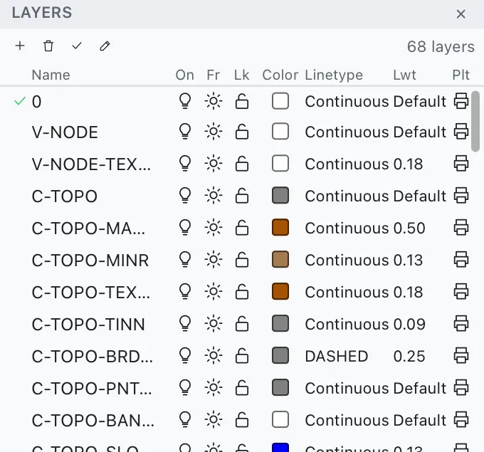
C-TOPO-MAJR; see Standards and styles.Civil objects use these same layers, so turning C-TOPO-MINR off hides the minor contours everywhere. Layer States (LAYERSTATE) saves and restores a set of layer settings — say one for the plan sheet and one for the drainage sheet.
The View tab

- Navigate: Extents (zoom to everything), Window, Previous, Pan, Zoom In, Zoom Out, Regen. The mouse wheel zooms at the cursor, a middle-button (or Space) drag pans, and a double middle click zooms to the extents.
- Panels: show or hide Properties (⌘1), Layers, the command History (F2), the Project browser, the Profile View under the plan, the Undo History, and open the Command Palette (⌘K).
- Model Viewports: split the plan into tiled views (Single, Two: Vertical, Four: Equal, Join, or Viewport Configuration).
- Display: Grid, Lineweights, Dynamic Input.
- Views & Coordinates: View Manager (named views), UCS, Isometric drafting.
Snaps and the status bar
The status bar along the bottom of the window shows, from the left, the cursor's coordinates, MODEL or PAPER, and the drafting toggles. Click a toggle (or press its key) to turn it on or off; a blue highlight means on.

| Toggle | Key | What it does |
|---|---|---|
| GRID | F7 | Shows a grid of dots in the plan. |
| SNAP | F9 | Makes the cursor jump in fixed steps. |
| ORTHO | F8 | Keeps lines horizontal or vertical. |
| POLAR | F10 | Guides the cursor along set angles. |
| OSNAP | F3 | Object snaps: the cursor locks to endpoints, midpoints, centers, intersections… of what's under it. Choose which in Drafting Settings (OSNAP, OS). |
| OTRACK | F11 | Tracks lines from snapped points, to line up with them. |
| LWT | Shows lineweights on screen. | |
| DYN | F12 | Dynamic input: prompts and typed values next to the cursor. |
| GROUP | Ctrl+Shift+A | Clicking one member of a group selects the whole group. |
Snaps work on civil graphics too: you can snap a dimension to a PI, or a polyline to the end of a corridor's edge of pavement.
The right of the status bar holds:

- Two annotation icons: Show annotative objects (
ANNOALLVISIBLE) and Add scales to annotative objects when the annotation scale changes (ANNOAUTOSCALE); hover for their names. - The Annotation scale of the current view (1:1 ▾); click it for a list of scales. In a layout, a viewport's scale, lock and maximize button come before it.
- The last civil update (Civil objects up to date, or Updated 1 object… after a change).
- What the drawing holds (17673 objects · 68 layers · Meters), and the gear icon, which opens Drafting Settings.
The Output tab: layouts and plotting

- Plot: Plot (⌘P) and the Page Setup Manager.
- Export: Export PDF, Save As (a Terrace project, DWG or DXF), Publish (several sheets into one PDF).
- Settings: drawing Units, Drafting Settings, Options.
- Reference: Attach a DWG/DXF as an external reference, Attach Image (an aerial photo or a scanned plan), the External References palette, Clip, Adjust, Frames.
- Manage: Open Drawing; Cleanup (Purge, Overkill, Rename); Styles (text, dimension, multiline and multileader styles, linetypes); Tools (QuickCalc, Data Extraction).
Layouts
The tabs under the plan — Model, Layout1, Plan and Profile - 1… — switch between model space (the full-size drawing) and layouts (paper sheets with viewports looking into it). In a layout the status bar reads PAPER and a Layout tab appears on the ribbon: New layout, Page Setup, viewports (Rectangular, Polygonal, Object, Clip, Lock), and Model Space / Paper Space / Maximize to work inside a viewport. The + after the tabs adds a layout.
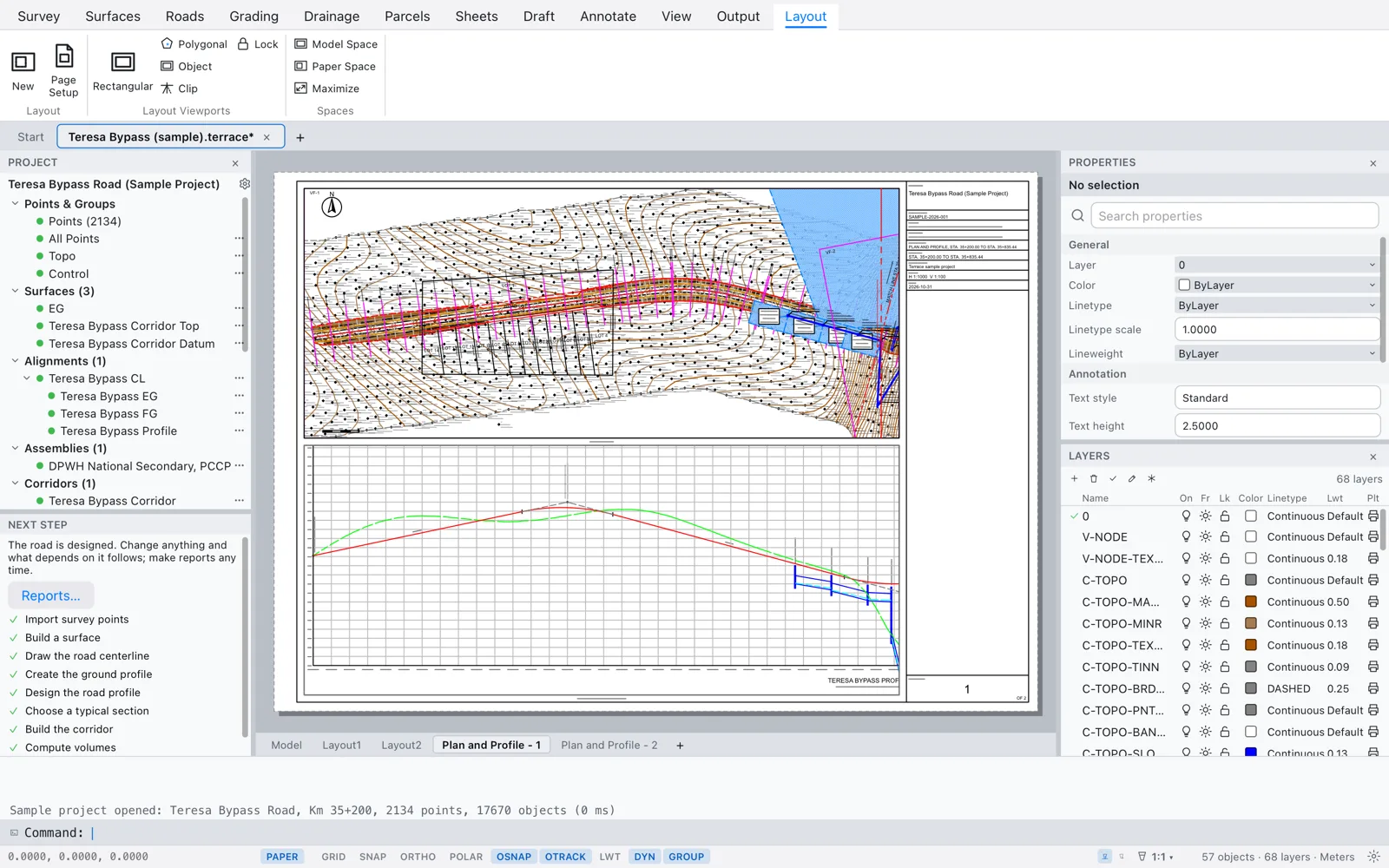
Plan-and-profile and cross-section sheets are layouts that Terrace makes for you; see Sheets and plotting. You can add your own notes and details to them like any layout.
Plotting
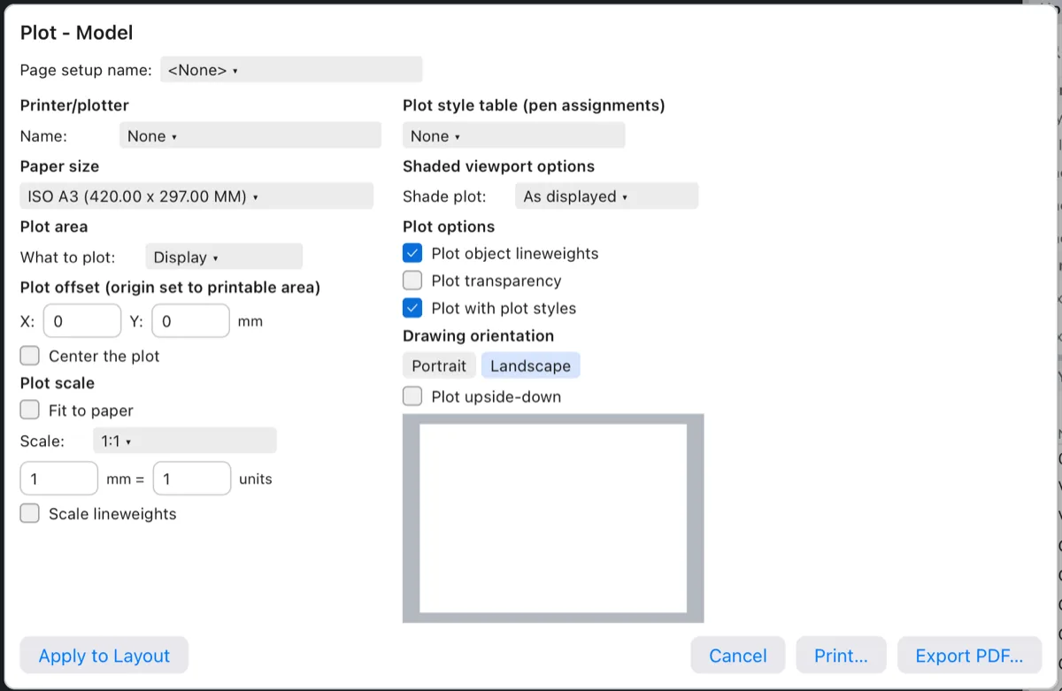
- Open the layout (or the Model tab) to print, and click Output ▸ Plot.
- Choose the Paper size, What to plot, the Plot scale (or Fit to paper), the plot style table (pen assignments) and the orientation. The preview shows where the drawing lands on the sheet.
- Click Export PDF… for a PDF, or Print…. Apply to Layout keeps the settings with the layout for next time.
How drafting and civil objects live together
Civil objects — surfaces, alignments, corridors, pipe networks, parcels — draw themselves as ordinary lines, arcs, text and hatches on their layers. Those graphics are rebuilt from the object whenever it changes, so Terrace protects them.
Civil graphics are protected
- These work on civil objects, as on the object itself:
MOVE,COPY,ROTATE,MIRRORandERASE, plus grips and the Properties panel. Moving an alignment's graphics moves its PIs, and everything built from it follows.ERASEfirst says what depends on the object and asks before deleting those too. - These leave civil objects alone:
EXPLODE,TRIM,EXTEND,STRETCH,SCALE,OFFSET,FILLET,CHAMFER,BREAK,JOIN,LENGTHEN,PEDIT,MATCHPROP,CHPROP,BLOCK,OVERKILLand the like. If your selection holds civil graphics, they're taken out and the command line says so; plain drawing objects in the same selection are still edited.

EXPLODE on the road: Terrace explains instead of breaking the object.Tip Need the civil linework as plain lines — for a detail or another program? Copy it with COPYCLIP and paste, or use ARRAY: copies made this way are plain drawing objects you can edit freely. Saving as DWG/DXF also turns everything into plain linework.
Polylines as inputs to civil commands
Drafting is often the first step of a civil design. Draw a polyline, then turn it into a civil object or use it as data:
| Draw this | Then use it in |
|---|---|
| A polyline along the road | CREATEALIGNMENT from a polyline: its vertices become PIs, curves added from the standard (Alignments). |
| Polylines or 3D polylines on ridges, ditches, edges | ADDBREAKLINES, ADDBOUNDARY, ADDCONTOURS on a surface (Surfaces). |
| A polyline around a pad or along a curb | FEATURELINE from a polyline, then GRADING (Grading). |
| Closed polylines for lots and the road right of way | CREATEPARCELS (Parcels). |
| A closed polyline around a drainage area | CATCHMENT by boundary (Drainage and water). |
| A polyline for a widening or a ditch line | A corridor target: when you edit the polyline, the corridor rebuilds by itself. |
After any drafting command that changes the drawing, Terrace updates whatever uses the changed objects, and the status bar reports the update.
Every drafting command, with its aliases, is in the command reference: Draw, Modify, Annotate, Layers, Blocks, Insert, Inquiry, View, File, Settings and Tools.