
Profiles
This chapter covers the vertical side of a road: the ground profile sampled from a surface, the profile view that shows it, and the design profile you draw with PVIs and vertical curves sized from the standard's K values. When you finish it you'll be able to design a grade line, adjust it live, read its design checks and print its PVI and vertical curve reports.
Profiles, PVIs, vertical curves and K
A profile is a line of elevations along an alignment: elevation against station. Terrace has two kinds you make yourself:
- a ground profile (existing ground, EG), sampled from a surface along the alignment;
- a design profile (finished grade, FG), the grade line of the road, which you draw.
You draw a design profile by its PVIs (points of vertical intersection), the corners where two straight grades meet. At each inside PVI Terrace puts a vertical curve, a parabola that eases the change of grade. A crest curve is over a hilltop; a sag curve is in a dip.
The algebraic difference of grades, A, is how much the grade changes at the PVI, in percent (from +1.67 % to −4.11 %, A = 5.78 %). The K value is the curve length per percent of A: K = L / A. The standard gives the smallest K for each design speed, so the driver can see far enough ahead over a crest, or far enough in the headlights in a sag. In a DPWH project at 60 km/h the minimum K is 11 on crests and 18 on sags, and every vertical curve must also be at least 60 m long (DGCS Vol 4 p.3-42).
Profiles are shown in a profile view: a grid drawn in the plan with stations across and elevations up, with the elevations exaggerated (ten times by default) so the grades are easy to see.
The profile tools
The profile tools are in the Profile group of the Roads tab. A selected alignment's contextual tab has Ground Profile and Profile View; a selected profile has its own contextual Profile tab with Design Profile, Profile View, Show Under Plan and the Properties, Zoom To and Report buttons.
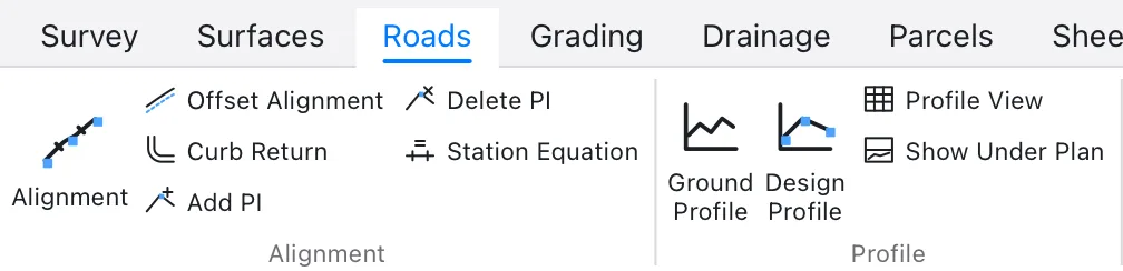
| Button | Command (aliases) | What it does |
|---|---|---|
| Ground Profile | CREATEPROFILE (EGPROFILE, CPROFILE) | Opens the Ground Profile dialog: samples a surface along an alignment |
| Design Profile | DRAWPROFILE (FGPROFILE, LAYOUTPROFILE) | Opens the Design Profile dialog: the finished grade as a best fit to the ground or a straight grade, or Click PVIs… to draw it in a profile view |
| Profile View | CREATEPROFILEVIEW (PROFILEVIEW, CPVIEW) | Opens the New Profile View dialog, or Place by Clicking… |
| Show Under Plan | — | Shows or hides the profile pane under the plan |
The buttons open their dialogs for the selected alignment (or the alignment of the selected profile or view; with nothing selected, the one in the profile pane). In the Next step panel, Create the ground profile and Design the road profile open the same dialogs. If you'd rather work at the command line, type the command: its first prompt offers a Dialog option (type D) that opens the dialog instead.
The ground profile from a surface
Before you design a grade line you need to know where the ground is. A ground profile reads the surface's elevations along the alignment, and stays linked: edit the surface or move a PI and it's sampled again by itself.
With the Ground Profile dialog
- Select the alignment (click it, or its name in the Project browser).
- Click Roads ▸ Ground Profile (also on the alignment's contextual tab), or Create the ground profile in Next step.
- Check the fields and click Create.
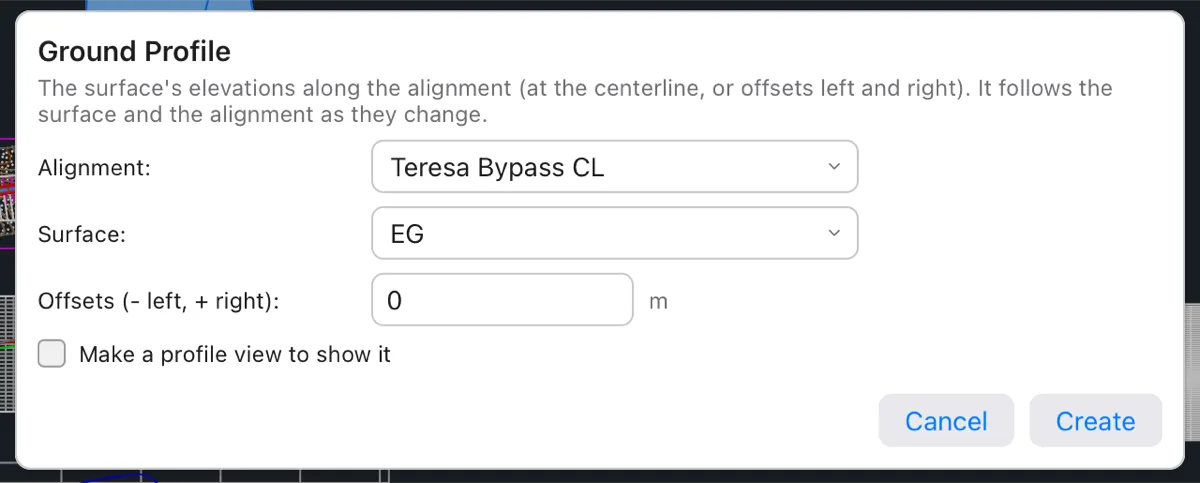
| Field | Default | What it does |
|---|---|---|
| Alignment | The selected one | The alignment to sample along. |
| Surface | The surface named EG, else the first surface | The surface to read. |
| Offsets (- left, + right) | 0 (the centerline) | One or more distances from the centerline. Type several, separated by commas (-10, 0, 10), to make one profile for each at once. |
| Make a profile view to show it | On when the alignment has no profile view yet | Places a new view below the alignment with all its profiles. When off, the new profiles are added to the alignment's views. |
The dialog names each profile after the alignment and the surface: Teresa Bypass CL - EG, and with an offset Teresa Bypass CL - EG R10.
With the command
- Type
CREATEPROFILE(EGPROFILE). - Pick the alignment: click it, type its name, or press Enter for the one in angle brackets (the selected one, or the last). Dialog (
D) opens the dialog instead. - Pick the surface. The default is the existing ground (the surface named EG, or the first surface that isn't made by a corridor).
- Type an offset from the centerline (+ right, − left), or press Enter for 0, the centerline itself.
- If the alignment has no profile view yet, Terrace offers to place one: move the outline and click its lower-left corner, or press Enter for no view (see Profile views).
The command names the profile after the surface and the alignment (EG - Teresa Bypass CL; with an offset, EG - Teresa Bypass CL R10), drawn on layer C-ROAD-PROF-EXST, and added to every profile view of the alignment. Terrace writes its station and elevation range, and warns when the surface doesn't cover the whole alignment.

If the project has no surface yet, Terrace tells you to build one first (see Surfaces). To sample another surface or offset later, select the profile and change Surface or Offset in Properties.
Profile views
A profile view is the graph you design in. It sizes itself to the alignment's stations and the profiles' elevations, with a grid row of margin above and below.
With the New Profile View dialog
Select the alignment and click Roads ▸ Profile View (also on the Alignment and Profile contextual tabs). The dialog fills in a place for the view below the alignment and below any views already there, with their left ends lined up.
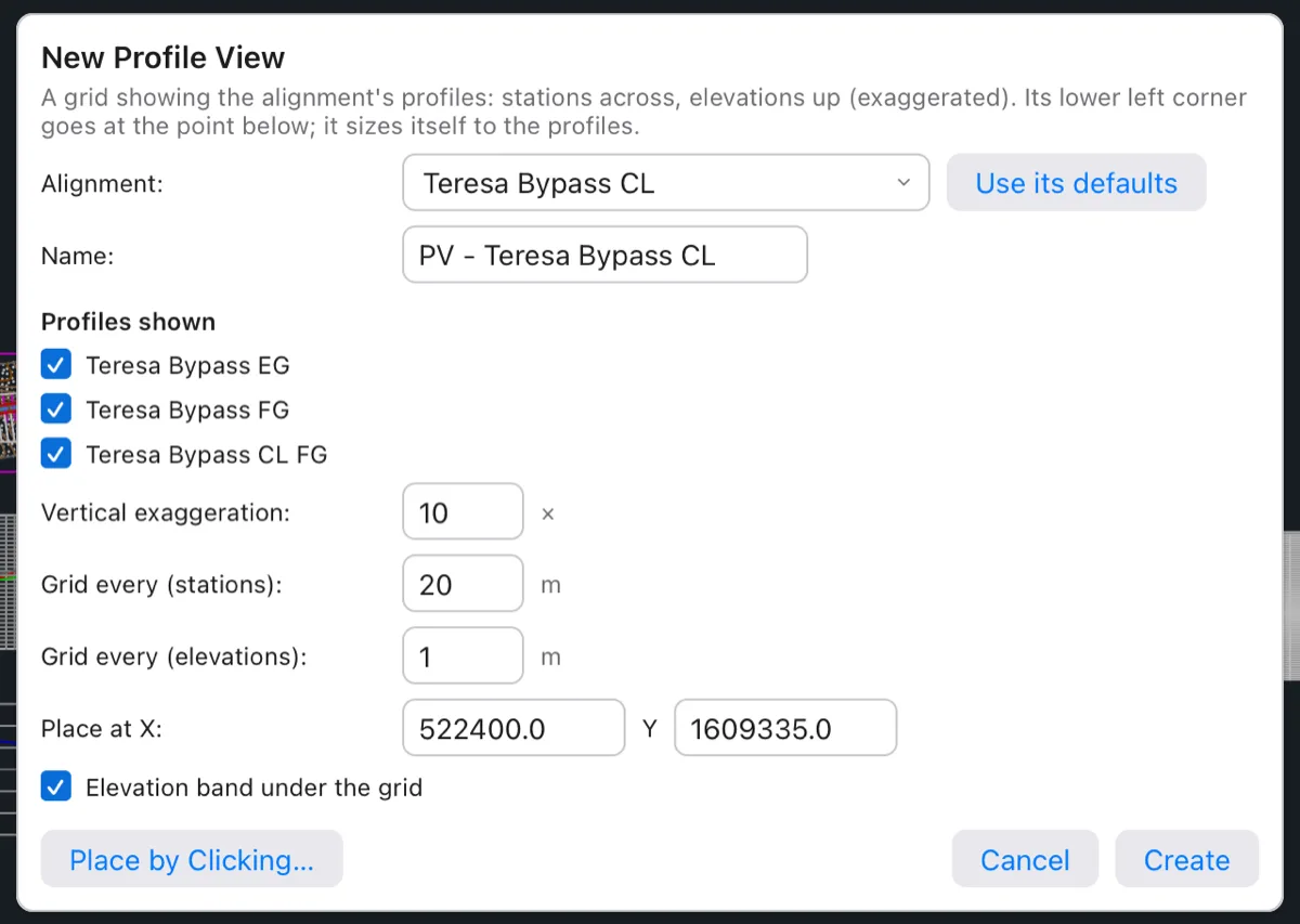
| Field | Default | What it does |
|---|---|---|
| Alignment | The selected one | Use its defaults fills the other fields again for the alignment you choose. |
| Name | PV - alignment | Must not be taken. |
| Profiles shown | All the alignment's profiles | Untick any you don't want in this view. |
| Vertical exaggeration | 10 | Vertical scale ÷ horizontal scale. |
| Grid every (stations), (elevations) | 20 m and 1 m (50 ft and 5 ft) | Grid spacing across and up. |
| Place at X, Y | Below the alignment | The lower-left corner of the view. |
| Elevation band under the grid | On | The table of ground and design elevations under the grid. |
Create makes the view and writes Profile view PV - Teresa Bypass CL made with 3 profiles.
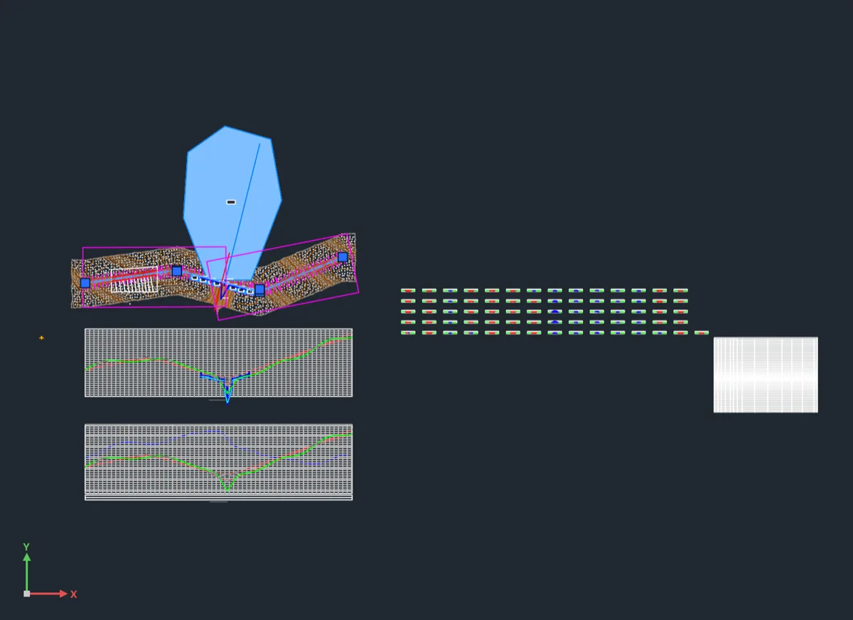
To put it somewhere else with the mouse, click Place by Clicking…: the dialog closes and CREATEPROFILEVIEW starts, as below.
By clicking
- Click Place by Clicking… in the dialog, or type
CREATEPROFILEVIEW(CPVIEW) and pick the alignment (Dialog,D, opens the dialog instead). - Move the cursor: the outline of the view follows it. Put it somewhere clear of the plan, usually below it.
- Click to place it.
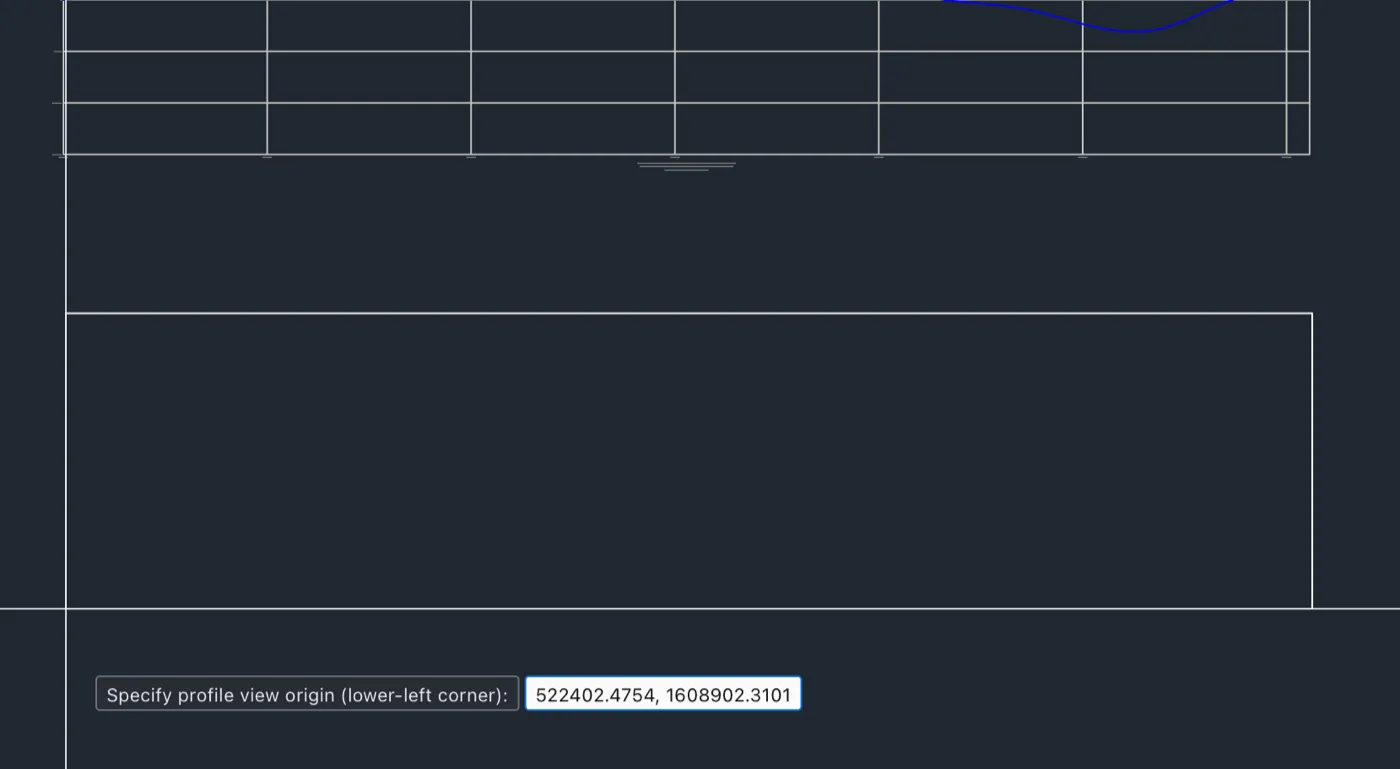
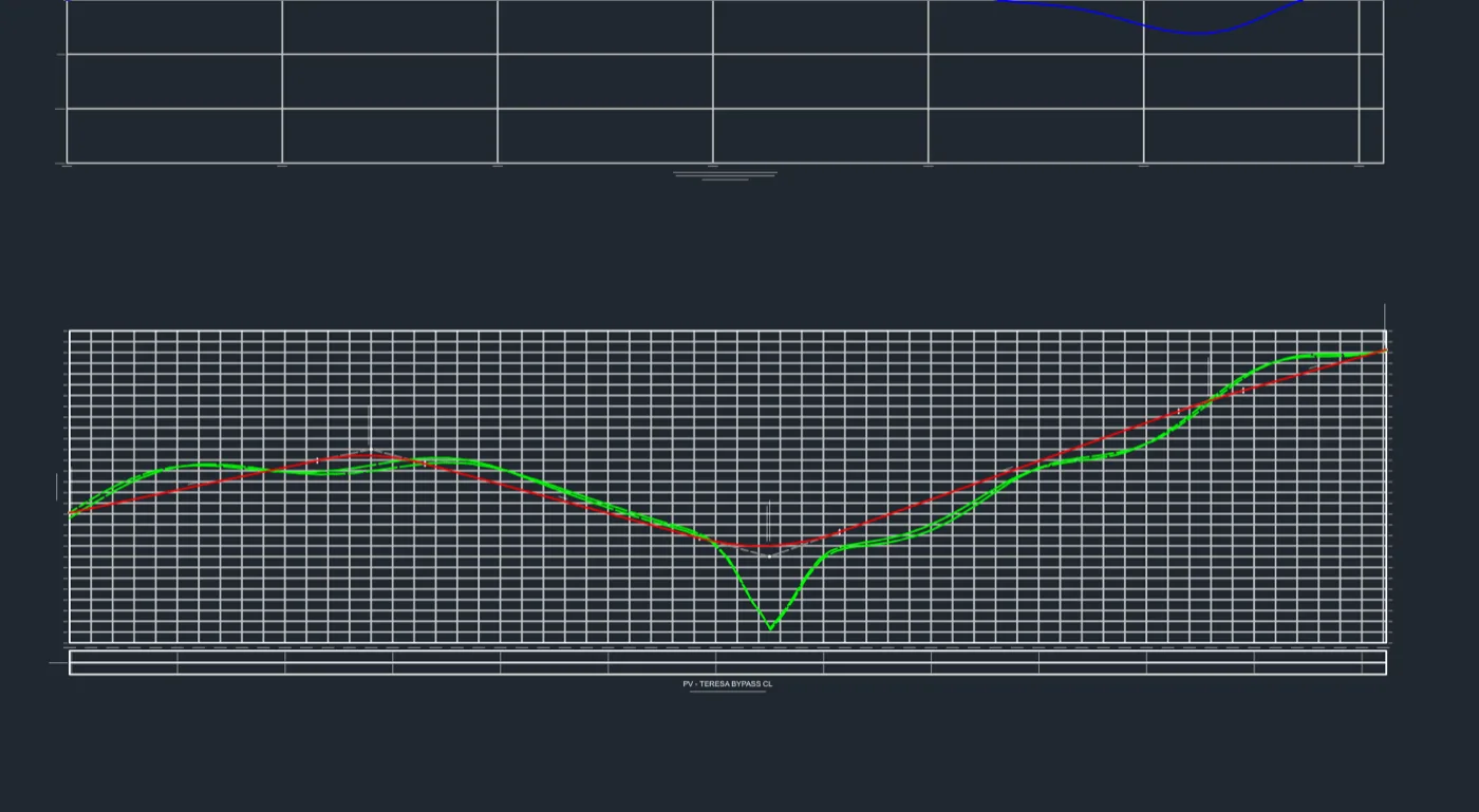
The new view is named PV - plus the alignment's name. It shows every profile the alignment has, with stations every 20 m and elevations every 1 m in the grid (100 ft and 5 ft in US projects), a vertical exaggeration of 10, a title, and an elevations band under the grid listing the ground and design elevations at each grid station. Profiles you make later are added to it.
Profile view Properties
Select the view to change it in Properties:
| Group | Row | What it does |
|---|---|---|
| General | Name | The view's name. |
| Style | How it's drawn. | |
| Alignment | Read only. | |
| Profiles shown | How many profiles it draws (read only). | |
| Graph | Vertical exaggeration | Vertical scale ÷ horizontal scale (10 = 1:1000 across, 1:100 up). |
| Grid across every | Station grid spacing. | |
| Grid up every | Elevation grid spacing. | |
| Stations | Whole alignment | On: the view covers the whole alignment. |
| From station, To station | When Whole alignment is off: the part to show. | |
| Elevations | Fit the elevations | On: the height follows the profiles. |
| Bottom, Top | When Fit the elevations is off: fixed elevations. |
To move a view, select it and drag its grip at the lower-left corner.
The profile pane under the plan
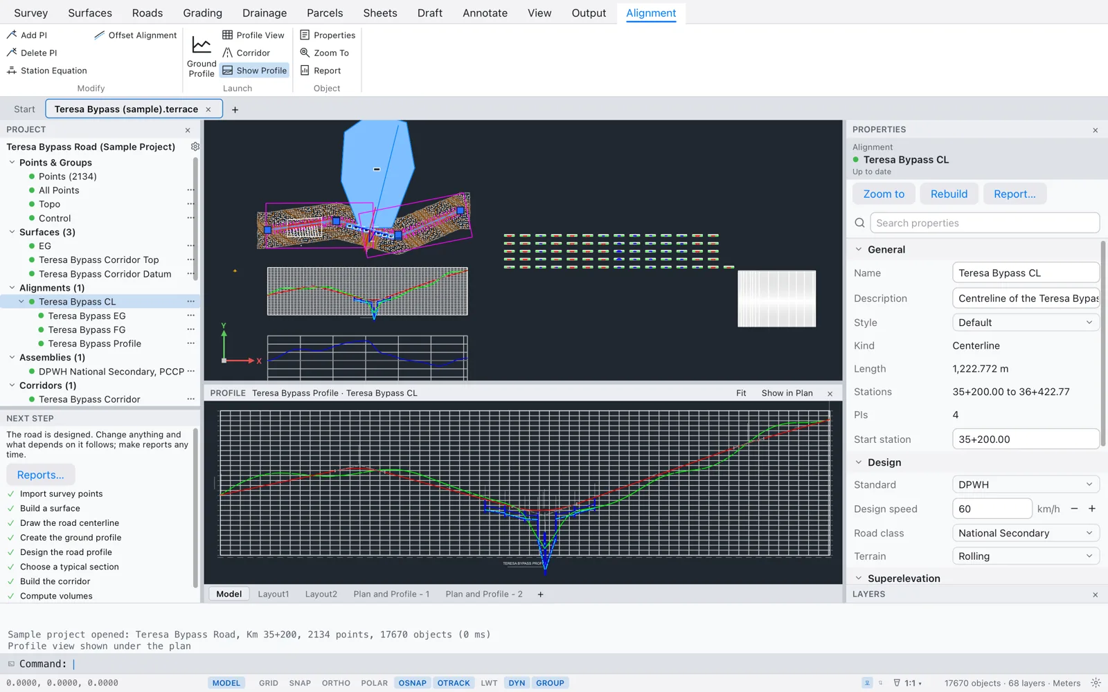
You don't have to scroll back and forth between the plan and the profile view: Terrace can show the profile view of the current alignment in a pane under the plan.
- Turn it on with Show Profile on the contextual Alignment tab, Show Under Plan on the Roads or Profile tab, or Show or Hide the Profile View in the command palette (⌘K).
- It follows the alignment you selected last (or the first alignment). Its title bar names the view and the alignment.
- Scroll to zoom, drag to pan, and double-click a point to centre the plan there. Fit fits the whole view; Show in Plan zooms the plan to the view, where you edit PVIs; × closes the pane.
- Drag the bar between the plan and the pane to make it taller or shorter.
- If the alignment has no profile view yet, the pane says so and offers Create Profile View, which starts
CREATEPROFILEVIEWto place one by clicking.
A first design profile from the dialog
The quickest start for a grade line is to let Terrace lay one out for you: a best fit through the ground profile, with curves sized from K. You then adjust it by dragging PVIs (see Editing).
- Select the alignment (or one of its profiles).
- Click Roads ▸ Design Profile (also on the Profile contextual tab), or Design the road profile in Next step. The Design Profile dialog opens.
- Choose how to start, check the numbers and click Create.
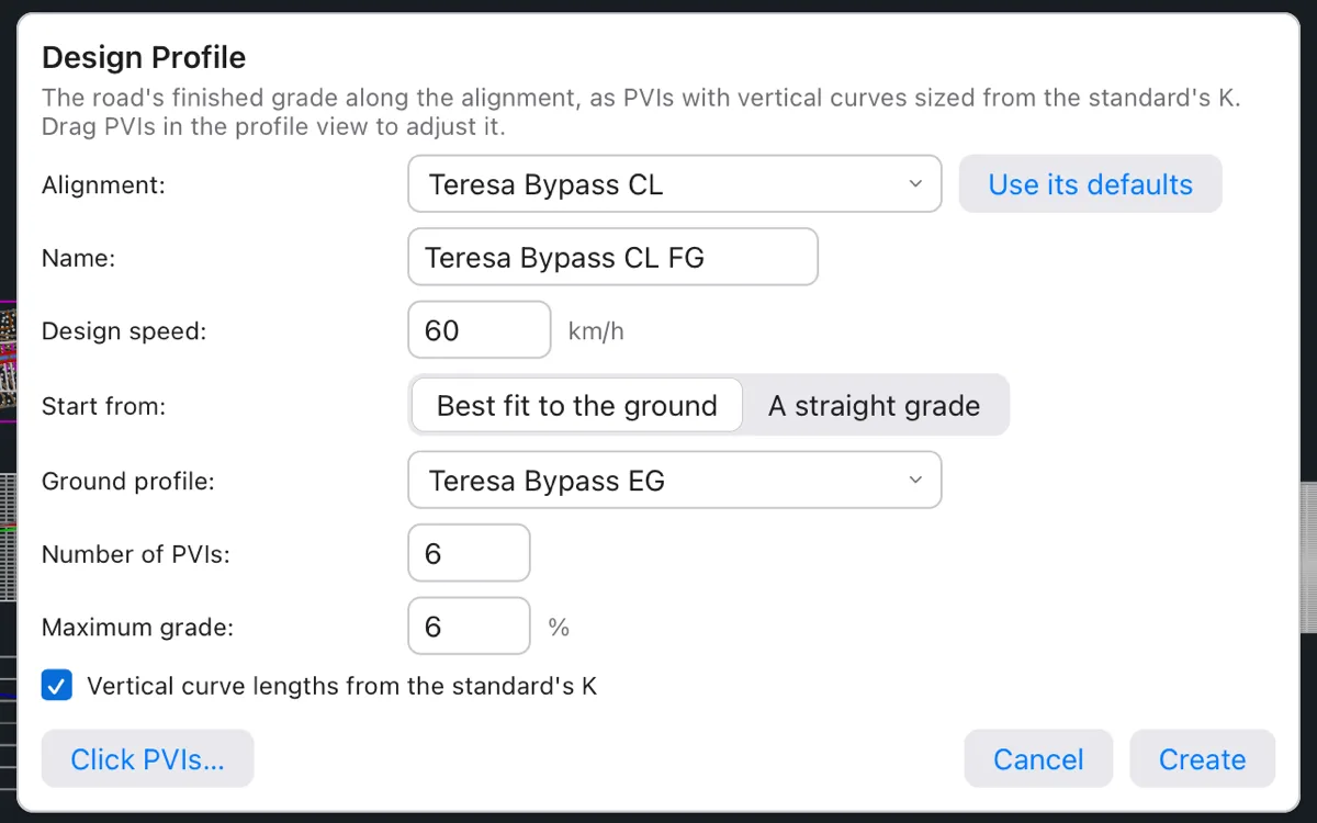
| Field | Default | What it does |
|---|---|---|
| Alignment | The selected one | Use its defaults fills the fields below again from the alignment. |
| Name | alignment FG | Must not be taken. |
| Design speed | The alignment's (60 km/h) | The speed the K values and checks use. |
| Start from | Best fit to the ground (A straight grade when there's no ground profile) | How the PVIs are made. |
| Ground profile | The alignment's first ground profile | The ground to fit, or to take the end elevations from. |
| Number of PVIs | One per 250 m of alignment plus 2, at least 3 (6 for the 1.2 km sample road) | Best fit only: how many PVIs, ends included. |
| Maximum grade | The standard's maximum for the speed and the alignment's terrain (6 % at 60 km/h, rolling, DPWH) | Best fit only: no grade steeper than this. |
| Start elevation, End elevation | Empty = the ground's elevation there | Straight grade only: the two ends of the grade line. |
| Vertical curve lengths from the standard's K | On | Gives each inside PVI a curve of the length the standard asks for (below). Off: no curves. |
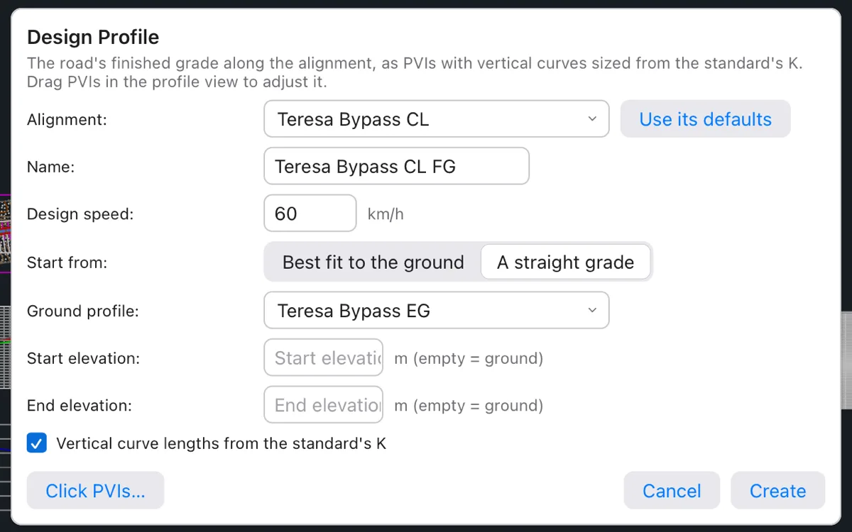
With the curves from K, each curve is L = K × A for the speed, at least the standard's minimum length (60 m for DPWH), rounded up to 10 m (50 ft), and never longer than the shorter of its two tangents. The profile is added to the alignment's profile views and their elevation bands, checked, and Terrace writes, for example, Design profile Teresa Bypass CL FG: 6 PVIs, 1 design problems (see Properties). If the alignment has no view yet, it reminds you to make one.
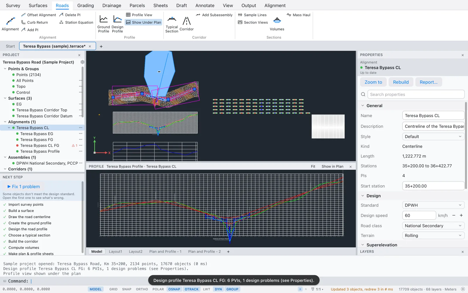
A best fit is a starting point, not a finished design: look at its problems (see Design checks) and move PVIs where the road must clear a culvert or meet a fixed level. To draw the grade line yourself instead, click Click PVIs…: the dialog closes and DRAWPROFILE starts (next section).
Drawing the grade by clicking PVIs (DRAWPROFILE)
The design profile is the road's finished grade at the centerline. You draw it in a profile view by clicking PVIs from left to right, over the ground line, and Terrace sizes the vertical curves for you.
- Click Click PVIs… in the Design Profile dialog, or type
DRAWPROFILE(FGPROFILE). Pick the profile view: click inside it, type its name, or press Enter for the one in angle brackets. (At this first prompt, Dialog,D, opens the dialog instead.) - Terrace writes the design speed and the crest and sag K values it will use (11 and 18 at 60 km/h in a DPWH project). The speed is the alignment's (or its road class's).
- Click the start of the grade line. A click near the start of the alignment (within 1 % of its length) snaps to the first station.
- Click each PVI. After each one Terrace writes its station, elevation and the grade from the last PVI (
PVI 2 at 35+498.51, elevation 60.302 m, grade 1.67%). The design line, with its curves, follows the cursor. - Click the end. A click near the end of the alignment snaps to the last station and finishes the profile. Otherwise press Enter after the last PVI.
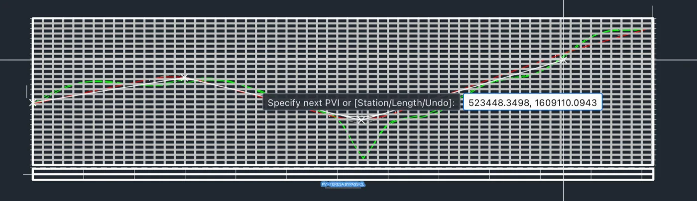
The prompt's options:
| Option | What it does |
|---|---|
| Station | Type a PVI as station and elevation instead of clicking: 36+422.77,70.25. |
| Length | Sets the vertical curve length at the last PVI you placed (once there are two or more). Press Enter at its prompt to go back to the length from K. |
| Undo | Takes the last PVI back. |
Stations are rounded to 0.01 m and elevations to 0.001 m, and each PVI must be further along than the last.
Curve lengths from K
Unless you set a length, each vertical curve is made as long as the standard asks: L = K × A with the crest or sag K for the design speed, at least the standard's minimum length (60 m for DPWH), rounded up to 5 m (10 ft). A curve is never made longer than the shorter of its two tangents. Where the grade hardly changes (A under 0.05 %) there's no curve.
When you finish, the profile is named FG - plus the alignment's name, drawn on layer C-ROAD-PROF-FG, added to the view and its elevation band, and checked. Terrace lists each curve:

In this example the sag at PVI 3 needs 18 × 5.42 = 97.6 m, rounded up to 100 m. The crest at PVI 2 needs only 11 × 4.1 = 45 m, so it gets the DPWH minimum of 60 m.
Editing PVIs and curves with grips
Select a design profile (click its line in the view, or its name in the Project browser) and its grips appear in the first profile view that shows it: a square at each PVI, and one at the end of each vertical curve (the PVT) for its length.
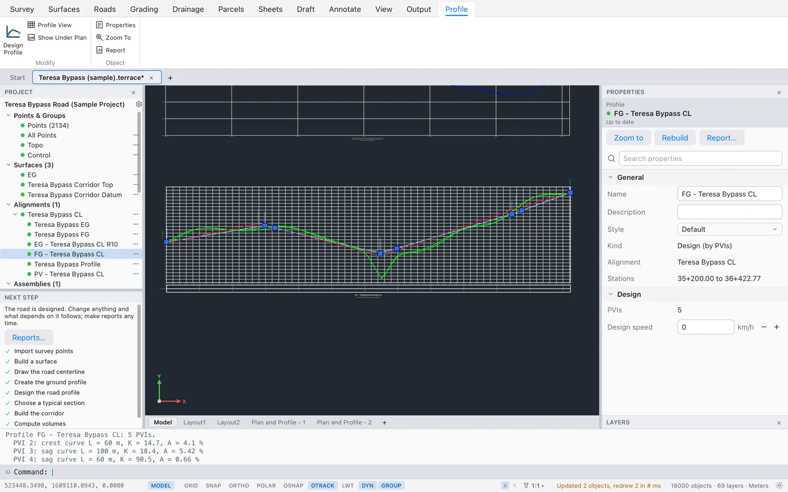
- Click a grip. The command line names it (
** PVI 3 **). - Move the cursor. The profile, its curves, and everything built on it are redrawn as you move.
- Click to put it down. It's one undo step.
A PVI grip moves the PVI in station and elevation; it can't pass its neighbours. A curve grip sets the curve length (twice the distance from the PVI), never more than the room between the neighbouring PVIs; you can also type the length and press Enter. A curve length you set by grip stays as you set it when the PVIs move, so watch the K checks.
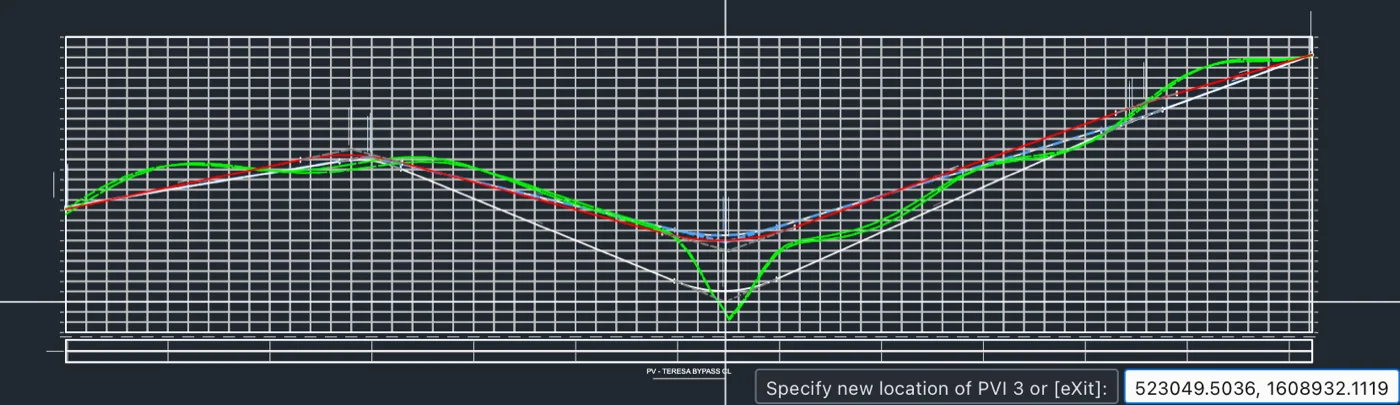
Note A profile counts as one object for grips, however long it is; grips are hidden only when more than 100 objects are selected at once.
K values, sight distance and the problems list
A design profile is checked against the standard at its design speed every time it changes. It uses the profile's own Design speed, or the alignment's when that is 0, and the alignment's terrain. The checks are:
- Grades: each grade against the maximum for the speed and terrain.
- K: each crest and sag curve against the minimum K. If K is fine, the curve length against the minimum length (60 m for DPWH).
- Sight distance: on crests, the distance a driver's eye (1.08 m high) can see an object 0.60 m high over the curve; on sags, the distance lit by headlights 0.60 m high. Either one must be at least the stopping sight distance for the speed (85 m at 60 km/h).
Problems are listed like an alignment's: on the command line, with a red dot and a count in the Project browser, at the top of Properties with Zoom to links, in the reports, and as Fix N problems in Next step.
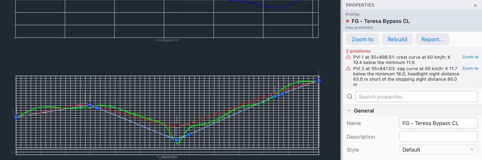
Note The problem messages count PVIs from 0, so PVI 1 there is the second PVI, the one the command line, grips and reports call PVI 2.
To fix K problems, lengthen the curve with its grip or flatten the grades by moving PVIs. Lowering the design speed in Properties lowers the minimum K, but only do that if the road really is designed for the lower speed.
Profile Properties
| Group | Row | What it is |
|---|---|---|
| General | Name, Description | Free text. |
| Style | How it's drawn. | |
| Kind | Existing ground (from a surface), Design (by PVIs), Corridor or Superimposed (read only). | |
| Alignment | Read only. | |
| Stations | Its first and last station (read only). | |
| Sampling (ground profiles) | Surface | The surface it samples. |
| Offset | Distance from the centerline, + right, − left. | |
| Design (design profiles) | PVIs | How many (read only). |
| Design speed | The speed its checks and K values use; 0 = the alignment's. |
The PVI and vertical curve reports
Select a profile and click Report on its Profile tab (or Report… in Properties). The Reports dialog opens on Profile PVIs; Vertical curves is just below it in the list.
| Report | Columns |
|---|---|
| Profile PVIs | PVI, station, elevation, grade in, grade out, A, curve length and K; the design checks are listed under the table. |
| Vertical curves | For each curve: crest or sag, PVC, PVI and PVT stations and elevations, length, grades in and out, A, K, and the station and elevation of the high or low point. |
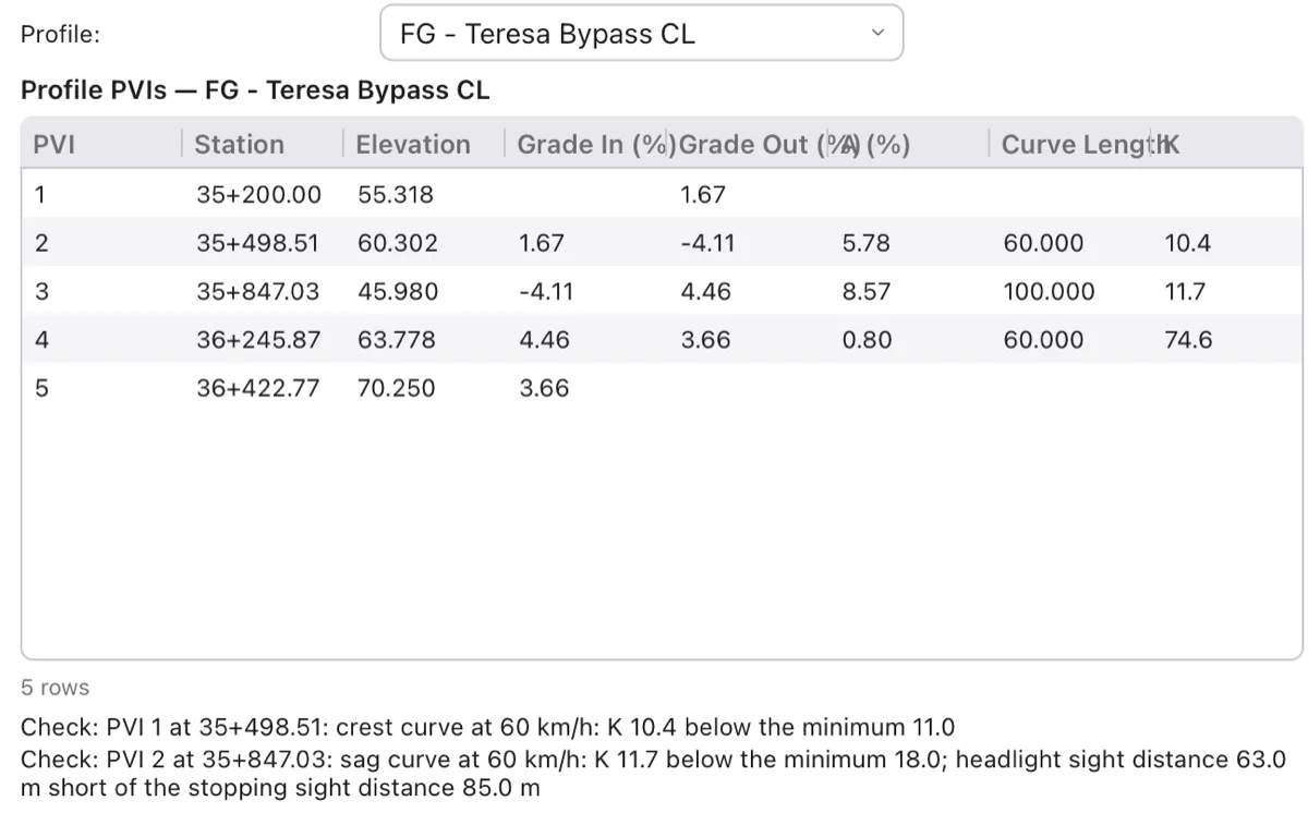
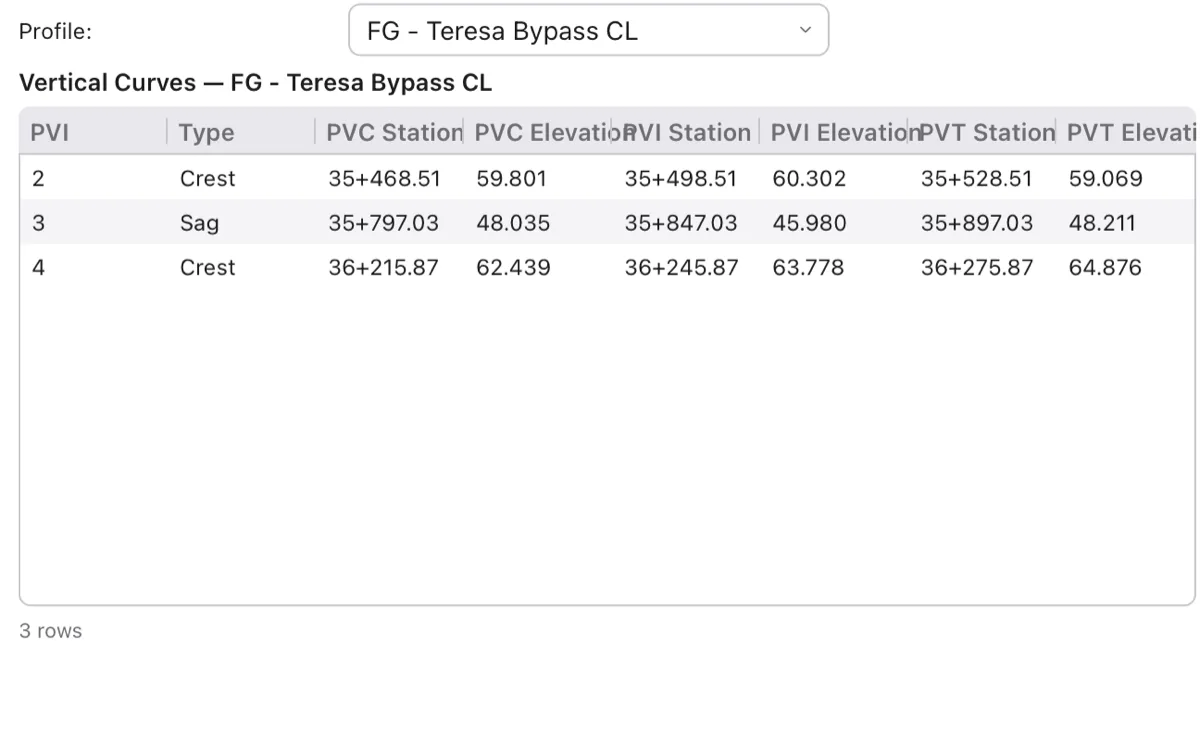
Save either with Save CSV… or Save PDF…, or Copy it. See Reports for the dialog.
What's next
With the alignment and its design profile done, choose a typical section and build the corridor: see Typical sections and corridors.