
Surfaces
This chapter shows how Terrace models the ground: building a TIN surface from survey points, shaping it with breaklines, boundaries and edits, showing it as contours or colored bands, and measuring cut and fill between two surfaces. You'll be able to make the existing ground (EG) surface every road, grading and drainage design stands on, and check volumes against it.
What a surface is
A surface is a model of the ground (or of a design) that gives an elevation anywhere inside it. Terrace builds most surfaces as a TIN, a triangulated irregular network: the survey points are joined into triangles (Delaunay triangulation, which keeps the triangles as even as it can), and the elevation between points is read off the flat triangle face. Contours, profiles, sections, daylight lines and volumes are all read from those triangles.
A surface is built from its definition: point groups, breaklines, contour data, boundaries and edits. Terrace keeps the definition, not just the triangles, so when a point moves, a group gains a shot or a breakline changes, the surface rebuilds by itself, and so does everything made from it (profiles, corridors, volumes).
There are three kinds:
- Triangles (TIN): from points and lines. The usual kind.
- Grid: a regular grid of elevations from a DEM file, triangulated for display (see Point clouds and grids).
- Volume (difference): one surface minus another, showing the depth of cut and fill (see Volumes).
The Surfaces tab
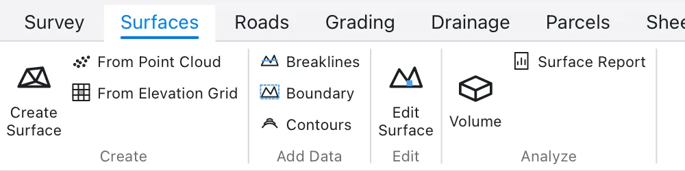
| Button | Command (aliases) | What it does |
|---|---|---|
| Create Surface | CREATESURFACE (CSURFACE, TINSURFACE) | Opens the New Surface dialog: a TIN from a point group |
| From Point Cloud | IMPORTLAS (LASIN) | A surface from a LAS/LAZ cloud |
| From Elevation Grid | IMPORTDEM (DEMIN) | A grid surface from a GeoTIFF or ASCII grid |
| Breaklines | ADDBREAKLINES (BREAKLINES, ADDBL) | Polylines or feature lines the triangles must follow |
| Boundary | ADDBOUNDARY (SBOUNDARY) | Outer, hide, show or data boundaries from closed polylines |
| Contours | ADDCONTOURS (CONTOURDATA) | Polylines at their elevations as contour data |
| Edit Surface | SURFACEEDIT (SEDIT, EDITSURFACE) | Add or delete TIN points, swap or delete edges, raise, lower, simplify, smooth |
| Volume | SURFACEVOLUME (SVOLUME, VOLSURFACE) | Cut and fill between two surfaces, optionally kept as a volume surface |
| Surface Report | — | The report dialog for the selected surface |
When you select a surface, a contextual Surface tab appears at the end of the ribbon with the same edit commands and an Object group: Properties, Zoom To and Report.

Creating a surface from points
The first surface of a project is normally the existing ground, EG, built from the survey's ground shots. The fastest way is the Build a surface from the group box when you import the point file. To build one from points already in the project:
- Click Surfaces ▸ Create Surface (or Build a surface in the Next step panel). The New Surface dialog opens, filled in.
- Check the Name and Description. The first surface of a project is called EG, “Existing ground”; later ones Surface, then Surface 2, Surface 3 ….
- Pick the group in From point group. Terrace starts with the project's every-point group (All Points), else the first group; the line below says how many points the group holds. A project without groups has no menu here: the surface takes every point, and Terrace makes an All Points group for it.
- Choose a Style (Standard at first; see Styles).
- Set Minor contours every and Major contours every: 0.5 m and 2.5 m to start (1 ft and 5 ft in a US project).
- Set Longest triangle side to trim long outside triangles (
0, the default, keeps them all; see the tip under Surface Properties). - Click Create.
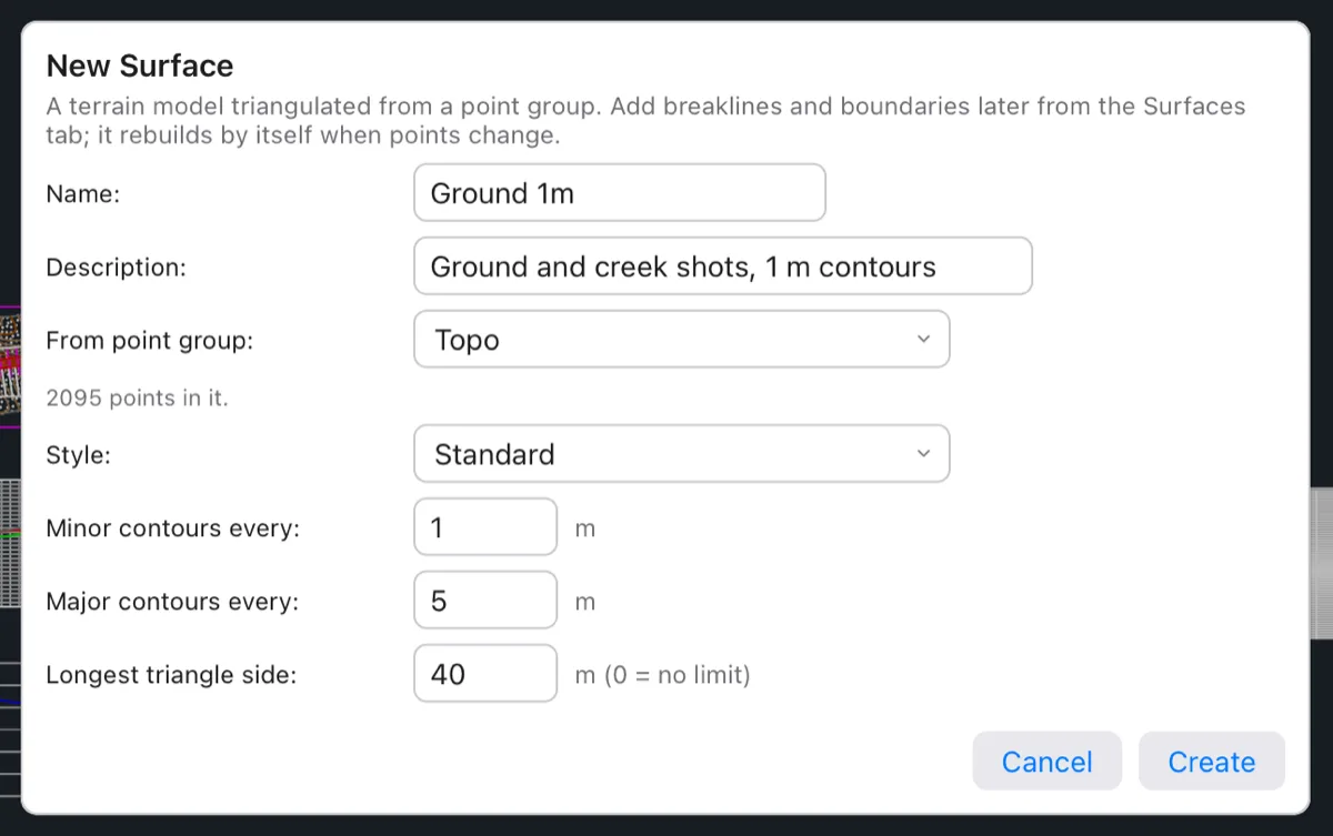
Terrace triangulates at once and reports the points, triangles and elevation range (“Surface Ground 1m: 2090 points, 4037 triangles, elevations 42.74 to 74.87.”). Points without an elevation are left out, and the surface's notes say how many. The surface appears under Surfaces in the Project browser, drawn on the C-TOPO layers. It's one undo step. The dialog refuses an empty or used name, a major interval smaller than the minor one, and a group with fewer than three points.
On the command line
Or type CREATESURFACE (alias CSURFACE):
- At Surface name [Dialog], press Enter for the suggested name or type one. Type D (Dialog) to open the New Surface dialog instead.
- At Build from (2134 points in the project) [All points/Group/Empty], choose:
- Enter or A: every point. Terrace uses (or makes) an All Points group for it.
- G: a point group. Type its name (or click it in the Project browser); the default is the last group.
- E: empty, to fill later with contours or breaklines.
- At Contour interval (major every 5), press Enter for 0.5 m (1 ft in a US project) or type another. The major contours are every fifth: 2.5 m.

Tip Build EG from a group of ground shots, not from every point. In the sample project, Topo takes only codes NGL* and CRK*, so tree, control and structure shots don't distort the ground. See Point groups.
The sample project's EG
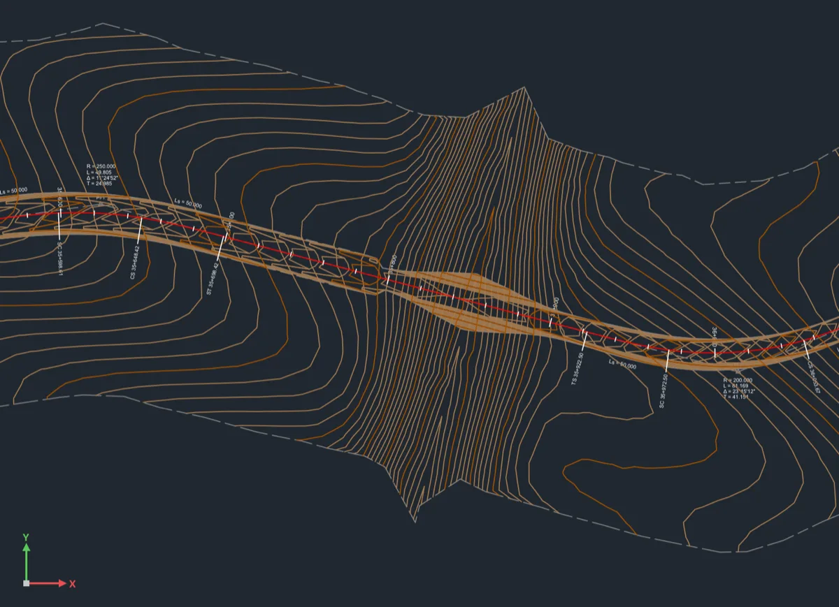
Open the sample project (Help ▸ Open the Sample Project) to see a finished one. EG is built from the Topo group (2,096 shots of rolling ground in Barangay San Roque, Teresa, Rizal), with the creek bed as a breakline and a longest edge of 40 m, contoured every 0.5 m with 2.5 m majors. The corridor adds two more surfaces, Teresa Bypass Corridor Top and Teresa Bypass Corridor Datum.
Surface Properties
Click a surface in the Project browser (or in the plan) to see it in Properties. Every change is one undo step and redraws at once.
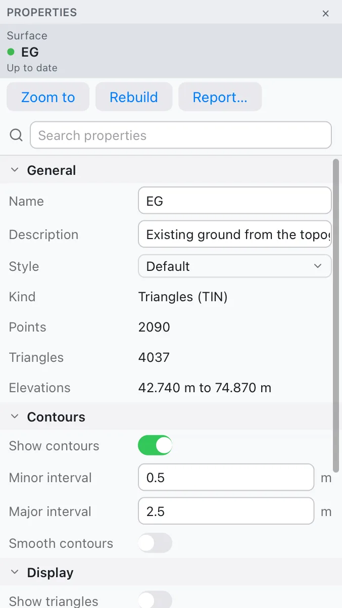
| Group | Row | What it does |
|---|---|---|
| General | Name, Description | The surface's name (profiles and corridors show it) and a note. |
| Style | How it looks (see Styles). | |
| Kind | Triangles (TIN), Grid, or Volume (difference). | |
| Points | Vertices of the built TIN. | |
| Triangles | Triangles of the built TIN. | |
| Elevations | Lowest to highest. | |
| Contours | Show contours | On by default. |
| Minor interval | 0.5 m by default. Can't be more than the major interval. | |
| Major interval | 2.5 m by default. Can't be less than the minor interval. | |
| Smooth contours | Draws each contour as a smooth curve through its straight pieces (it still passes through every vertex). | |
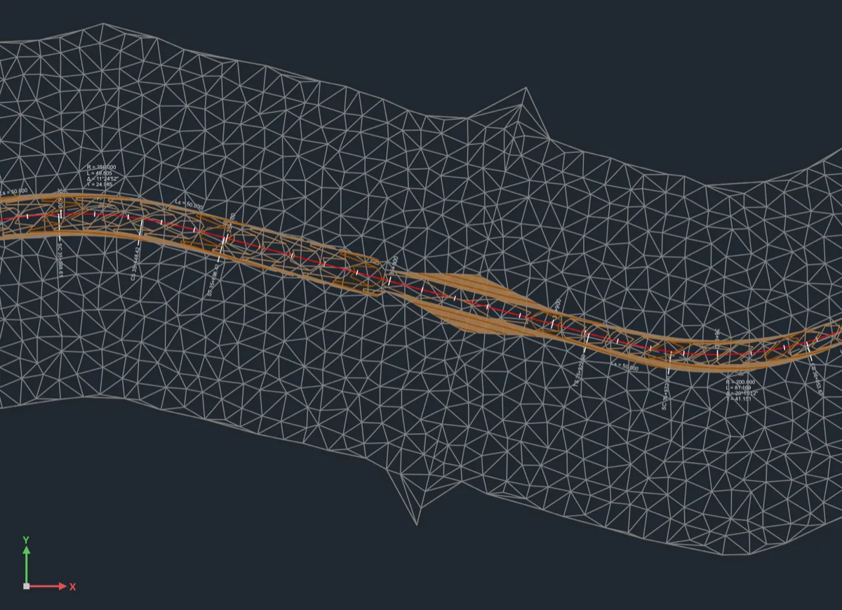
| Display | Show triangles | The TIN's edges, on layer C-TOPO-TINN. |
| Show points | The TIN's vertices, on C-TOPO-PNTS. | |
| Show border | The outside edge, dashed, on C-TOPO-BRDR. On by default. | |
| Analysis | None, Elevation bands or Slope bands (see Elevation and slope bands). | |
| Build | Longest edge | Triangles at the outside with an edge longer than this are left out (0 = keep all). TINs only. |
| Don't rebuild by itself | Locks the surface: it keeps its triangles when its points or lines change, until you click Rebuild. |
The buttons at the top: Zoom to fits the surface in the view, Rebuild builds it again now, Report… opens its statistics report.
Tip A survey band along a road has a ragged outside, and the triangulation bridges the gaps with long thin triangles that invent ground nobody surveyed. Set Longest edge to about twice your shot spacing (the sample uses 40 m) to trim them, or draw an outer boundary.
Contours and intervals
Contours are drawn from the triangles at every multiple of the minor interval: minor ones on layer C-TOPO-MINR, every major one (each multiple of the major interval) heavier on C-TOPO-MAJR. Terrace's default, 0.5 m minor and 2.5 m major, suits the 1:1000 plans DPWH road plans use.
- Select the surface and set Minor interval and Major interval in Properties (for example 1 and 5 for steep ground).
- Turn on Smooth contours for a hand-drawn look on a presentation plan.
If an interval would give too many contours for the surface's height range, Terrace doubles it for drawing until they fit, so a tiny interval on a mountain doesn't freeze the plan.
Note The styles Contours 1m and 5m, Contours 0.5m and 2.5m and Contours 2ft and 10ft carry their own intervals, and those win over the Properties rows. Use the Default or Standard style when you want to set the intervals yourself.
Styles
A style sets what a surface shows. Pick one from Style in Properties; change the styles themselves in Output ▸ Styles (see Standards and styles).
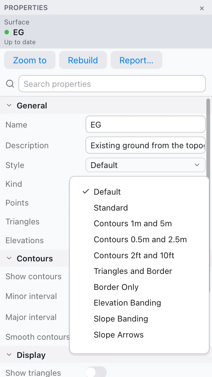
| Style | Shows |
|---|---|
| Default / Standard | Contours at the surface's own intervals, and the border. |
| Contours 1m and 5m, 0.5m and 2.5m, 2ft and 10ft | Contours at those intervals, no triangles. |
| Triangles and Border | The TIN's edges and border, no contours: for checking the triangulation. |
| Border Only | Just the outline. |
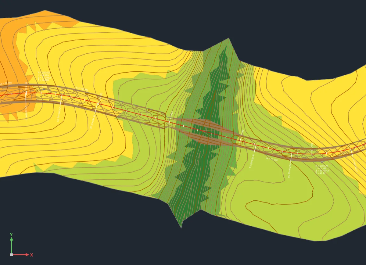
| Elevation Banding | Eight colored elevation bands, with contours. |
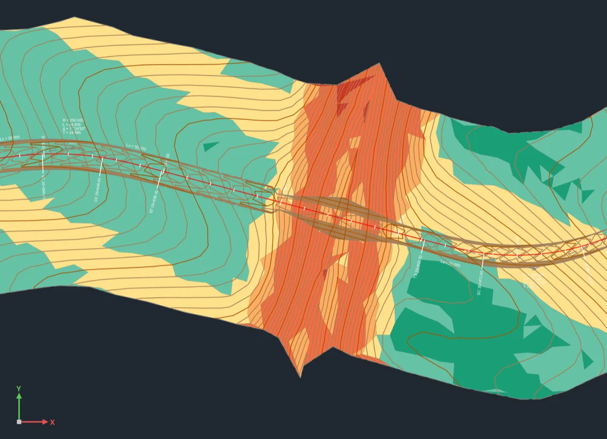
| Slope Banding | Colored slope bands (2, 5, 10, 15, 25, 50 %), no contours. |
| Slope Arrows | An arrow pointing downhill on each triangle, with contours. |
Elevation and slope bands
Colored bands make the shape of the ground readable at a glance: where the high ground is, which slopes are too steep to cut, where water will gather. Set Analysis in Properties (or pick a banding style).
- Elevation bands: the surface's range split into eight equal bands, low to high, on layer
C-TOPO-BANDunder the contours. - Slope bands: each triangle colored by its slope in bands with limits at 2, 5, 10, 15, 25 and 50 %.
Note The Analysis menu also offers Slope direction, but nothing is drawn for it yet. For downhill directions, use the Slope Arrows style.
Breaklines
A breakline is a line the ground changes slope along: a creek bed, a ridge, the top and toe of a bank, the edge of an existing road. Triangles are not allowed to cross it, so the TIN follows the feature instead of cutting corners across it. The sample's EG has the creek bed as a breakline.
- Draw the line as a polyline or line (
PLINE), or use a feature line (see Grading). - Click Surfaces ▸ Breaklines (or type
ADDBREAKLINES, aliasADDBL). - At Select surface to add breaklines to, press Enter for the ground surface (EG) or click or type another.
- At Select polylines or feature lines, pick them and press Enter.

What Terrace makes of each kind of line:
| You pick | It becomes |
|---|---|
| A feature line | A standard breakline with the feature line's 3D points, linked to it: change the feature line's elevations and the surface follows. |
| A polyline or line at an elevation (its Elevation property isn't 0) | A standard breakline at that elevation: its points and edges are forced into the TIN. |
| A polyline or line at elevation 0 | A non-destructive breakline: the edges are forced in, but the elevations along it come from the surface itself. Use it to make the triangles follow a line without changing the ground. |
Arcs in polylines are cut into short chords (at most 5° each). The surface rebuilds and the command line gives its new counts.
Tip For a breakline whose elevation changes along its length (a creek bed falling downstream), make it a feature line: it carries an elevation at every vertex.
Boundaries
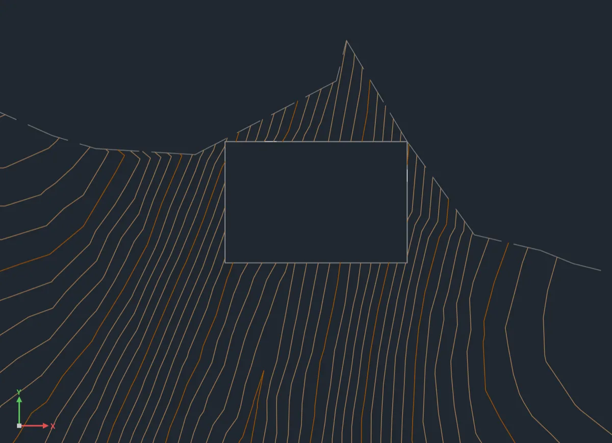
A boundary limits where a surface has triangles. Use an outer boundary to keep the TIN inside the surveyed area, and a hide boundary to cut out a building, a pond or anywhere the ground wasn't surveyed.
- Draw a closed polyline around the area (
PLINE, ending with C to close), or use a closed feature line. - Click Surfaces ▸ Boundary (or type
ADDBOUNDARY, aliasSBOUNDARY). - Press Enter for EG, or pick the surface.
- At Boundary type [Outer/Hide/Show/Data], choose the type (Enter = Outer).
- At Select closed polylines, pick them and press Enter.

| Type | Key | Effect |
|---|---|---|
| Outer | O | Triangles outside are removed. |
| Hide | H | Triangles inside are removed: a hole. |
| Show | S | Inside a hide boundary, triangles inside are kept again (an island in a pond). |
| Data | D | Its edges are forced into the TIN and the surface is clipped to it; points outside are left out. |
Boundaries clip exactly: triangles crossing the line are cut along it, with new vertices on the line. They're applied in the order you add them.
Contours as data
When the only ground data you have is an old contour map (digitized from a topographic map, or a DXF from a consultant), the contour lines themselves can build the surface.
- Make sure each contour polyline sits at its elevation (a polyline's elevation, not 0).
- Create an empty surface:
CREATESURFACE, then E (Empty) at Build from. - Click Surfaces ▸ Contours (or type
ADDCONTOURS, aliasCONTOURDATA), pick the surface and select the contour polylines.
Each polyline's vertices go in at its elevation, and its edges are kept. Terrace warns when some polylines are at elevation 0 (“check the polylines' elevations”): they are almost always contours whose elevation was never set. Feature lines can be added as contour data too.
Editing a surface
Sometimes the triangulation needs a hand: a bad shot makes a spike, an edge runs the wrong way across a ditch, a design pad needs raising. SURFACEEDIT changes the TIN directly.
- Click Surfaces ▸ Edit Surface (or type
SURFACEEDIT, aliasSEDIT). - At Select surface to edit, click the surface or type its name (for example
EG). - At Edit surface [AddPoint/DeletePoint/SwapEdge/DeleteLine/RaiseLower/SImplify/SMooth], choose an edit and follow its prompts. After each one you're back at this prompt; press Enter to finish.

| Edit | Key | What you do | What happens |
|---|---|---|---|
| Add point | AP | Click a location, then type the elevation (the default is the surface's there). Click the next one. | A new TIN vertex. |
| Delete point | DP | Click near a TIN vertex; repeat. | The nearest vertex is removed and the hole re-triangulated. The survey point itself stays. |
| Swap edge | SE | Click near an edge. | The edge between two triangles flips to their other diagonal. |
| Delete line | DL | Click near an edge. | The edge (and its triangles) is removed: for trimming outside triangles. |
| Raise/lower | RL | Type the change (negative lowers). | The whole surface moves up or down. |
| Simplify | SI | Type the largest elevation change allowed (default 0.05). | Points are removed while the surface moves no more than that: fewer triangles, same shape. |
| Smooth | SM | Type a grid spacing (default 5). | The surface is resampled on that grid by natural neighbor interpolation. |
After each edit the command line gives the new triangle count (“… triangles (was …)”). Edits are stored in the surface's definition and replayed, in order, every time it rebuilds, so they survive changes to its points.
Volumes between surfaces
Comparing two surfaces gives the earthwork between them: existing ground against a corridor top for a road, against a graded pad, or one survey against a later one to measure a stockpile or quarry. Terrace uses the composite (TIN-to-TIN) method: both TINs are merged and every prism between them is measured exactly.
- Click Surfaces ▸ Volume (or type
SURFACEVOLUME, aliasSVOLUME). - At Select base surface (existing ground), press Enter for EG.
- At Select comparison surface (design), press Enter for the suggestion (a corridor's top surface when there is one, else the last surface built) or pick another.
- At Cut factor (swell) and Fill factor (shrinkage), press Enter for 1 or type your factors. Cut volumes are multiplied by the cut factor, fill by the fill factor.
- Read the result, then answer Keep the difference as a volume surface? [Yes/No].

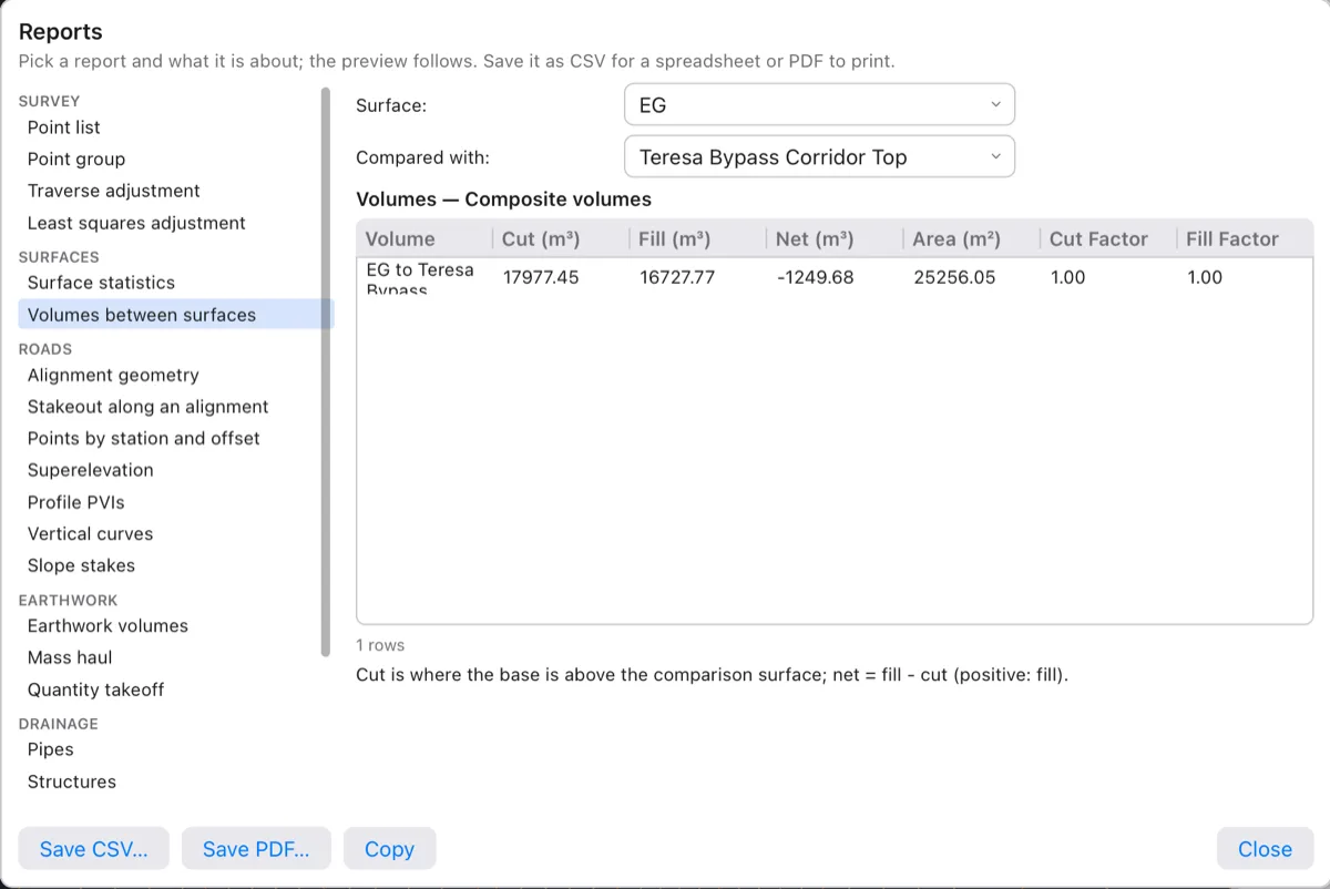
Cut is where the base is above the comparison surface (ground to dig away); fill is where it's below (ground to build up). Net = fill − cut: negative means the job has more cut than fill (a surplus to haul away or waste). The area is the plan area where both surfaces have triangles.
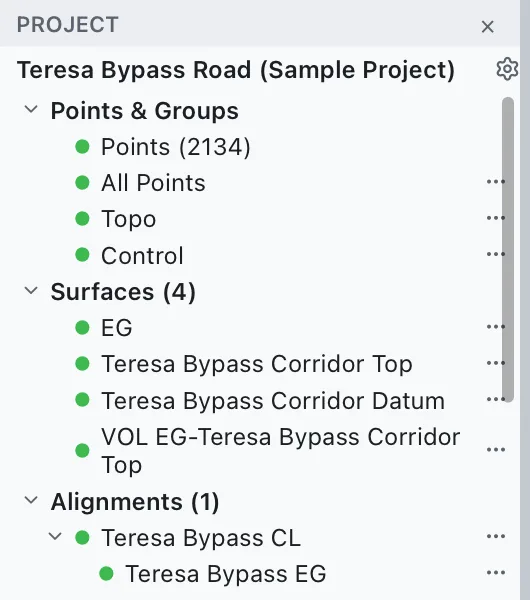
Answering Y keeps a volume surface named VOL EG-Teresa Bypass Corridor Top. Its elevation everywhere is the comparison minus the base, so its contours (0.5 m minor, 2.5 m major) are lines of equal cut or fill depth, and zero is the cut/fill line. Like every surface, it follows both surfaces when they change.
For volumes along a road by sections (average end area, DPWH pay items, mass haul), see Sections and earthwork.
Surface reports
Click Surfaces ▸ Surface Report with a surface selected, Report… in its Properties, or type REPORT and pick a report under Surfaces. Both save as CSV or PDF (see Reports).
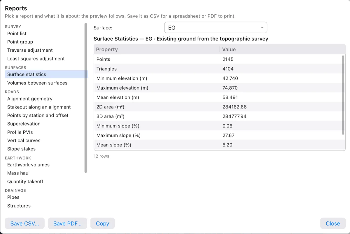
Surface statistics lists points, triangles, minimum, maximum and mean elevation, 2D and 3D area, minimum, maximum and mean slope (the mean weighted by plan area), and the corners of the surface's extent, with the surface's build notes below.
Volumes between surfaces gives cut, fill, net, area and the factors. Pick the Surface and the surface it is Compared with, or pick a volume surface to report its pair.
Point clouds and grids
Two more kinds of data make surfaces directly, and both are on the Surfaces tab as well as the Survey tab:
- From Point Cloud (
IMPORTLAS): a LiDAR or drone LAS/LAZ cloud, ground points (class 2) thinned to one per grid cell, becomes a TIN named after the file. - From Elevation Grid (
IMPORTDEM): a GeoTIFF or Esri ASCII grid DEM (an IfSAR or SRTM tile, say) becomes a grid surface.
Once made, they behave like any other surface: Properties, styles, contours, volumes and profiles all work. The import dialogs are covered in Point clouds and Elevation grids.